Collecting main for tubular cracking furnaces

a technology for collecting mains and cracking furnaces, which is applied in the direction of liquid spraying apparatus, lighting and heating apparatus, mixing methods, etc., to achieve the effects of reducing pressure loss, reducing creep flows, and reducing pressure loss

Active Publication Date: 2012-08-07
UHDE GMBH
View PDF20 Cites 2 Cited by
  • Summary
  • Abstract
  • Description
  • Claims
  • Application Information

AI Technical Summary

Benefits of technology

[0012]Surprisingly it has been discovered that, by means of the curved outlets and the consequential flow acceleration and homogenisation as well as with the associated decrease of the pressure loss in the collecting main, it was possible to notably reduce the creep flows within the insulation layer. This is due to the fact that the resulting reduced pressure loss, which involves no other advantage to the operation of the tubular cracking furnace, decreases the driving force for the creep flows due to the porosity of the insulation layer and hence also the heat amounts conveyed to the jacket tube.
[0015]the cross-sectional area of the gas outlet narrows towards its end. This will lead to higher gas velocities at the gas outlet,

Problems solved by technology

These small gas flows are also called creep flows which may convey considerable amounts of heat to the outer jacket tube where they produce local overheating.

Method used


Image

  • Collecting main for tubular cracking furnaces
  • Collecting main for tubular cracking furnaces

Examples


Embodiment Construction

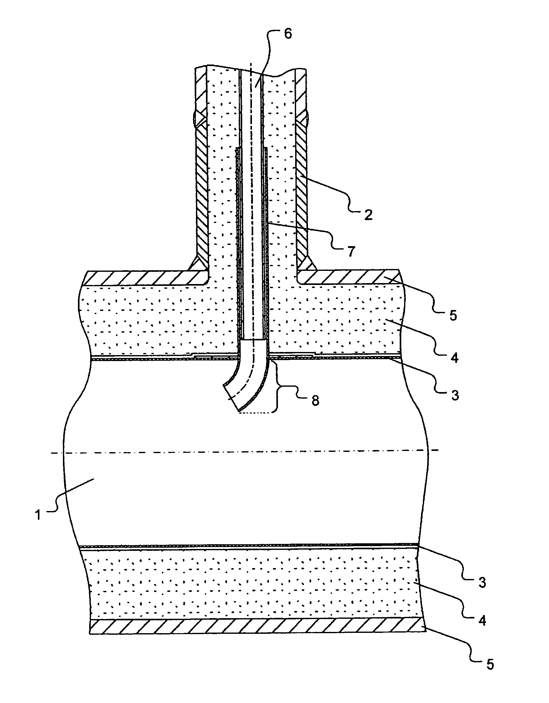
[0021]Nozzle 2 is arranged above collecting main 1. Collecting main 1 consists of three layers. The first layer is made up by metal inner tube 3, the second layer by insulation layer 4 which is made of refractory concrete, and the third outer layer which consists of the outer or jacket tube 5. Nozzles 2 (in this example there is only one nozzle) are arranged above collecting main 1. In the area of nozzle 2, process gas tube 6 from the furnace chamber, which is not shown, runs in a guide sleeve 7. In the example shown process gas tube 6 ends in the area of insulation layer 4 in guide sleeve 7. At its free end, guide sleeve 7 is shaped as a bend 8, the outlet opening of which points into the direction of the main flow of collecting main 1.

[0022]

List of references used1Collecting main2Nozzle3Inner tube4Insulation layer5Outer tube6Process gas tube7Guide sleeve8Pipe bend


PUM

PropertyMeasurementUnit
refractoryaaaaaaaaaa
areaaaaaaaaaaa
cylindrical shapeaaaaaaaaaa

Abstract

Collecting line for removing hot process gases conducted in process gas tubes from tubular reformers, wherein the collecting line has on the inside at least one insulation layer made of fire-resistant concrete or fire-resistant brick, and on the outside a wall made of a metallic outer tube, comprises a plurality of stubs via which the process gas tubes of the tubular furnace can be connected to the collecting line, wherein in the region of the stubs, the process gas tubes are at least in part conducted in guide tubes, and each gas outlet connected to the respective process gas tube projects into the collecting line, by means of which the process gas is introduced into the collecting line in correct functioning, and at least one gas outlet is constructed as a pipe bend.

Description

BACKGROUND OF THE INVENTION[0001]The invention relates to a collecting main for the discharge of hot process gases from tubular cracking furnaces as frequently used in natural gas reforming plants for the production of synthesis gas. Such collecting main is always provided with several nozzles via which the process gas tubes of the tubular cracking furnace can be connected to the collecting main. In the area of the nozzles, the process gas tubes usually run in guide sleeves. The gas outlets of the guide sleeves or process gas tubes end in the collecting main and extend into it. Under proper operating conditions the reaction gas is introduced into the collecting main via these gas outlets, the present invention providing at least part of the outlets in the form of pipe bends. Furthermore, the invention relates to the use of such collecting mains in a tubular cracking furnace.[0002]A plurality of tubular cracking furnaces is known which are used for the indirect heating of crackable f...

Claims


Application Information

Patent Timeline
Patent Type & Authority Patents(United States)
IPC IPC(8): B01J19/00F23J7/00B01F5/04F02M25/10B01F3/04
CPCB01J8/008B01J8/062C01B3/384C10G9/203B01J2208/00495B01J2208/00504B01J2219/00247C01B2203/0233C01B2203/0816
Inventor MEISSNER, OLIVERWODBERG, SILKE
Owner UHDE GMBH
Why Eureka
Try Eureka