
More electric engine with regulated permanent magnet machines

a permanent magnet machine and electric engine technology, applied in the direction of electric generator control, dynamo-electric converter control, electric devices, etc., can solve the problems of increasing the voltage level of the engine accessories compared to the other components, raising cost and weight, and harming efficiency

Active Publication Date: 2012-08-07
HAMILTON SUNDSTRAND CORP
View PDF35 Cites 15 Cited by
  • Summary
  • Abstract
  • Description
  • Claims
  • Application Information

AI Technical Summary

Problems solved by technology

One challenge with such a system is that the engine accessories tend to need increased voltage levels compared to the other components on the aircraft.
Providing such distinct voltage levels has proved challenging, and has raised cost and weight, as well as harming efficiency.

Method used


Image

  • More electric engine with regulated permanent magnet machines
  • More electric engine with regulated permanent magnet machines

Examples


Embodiment Construction

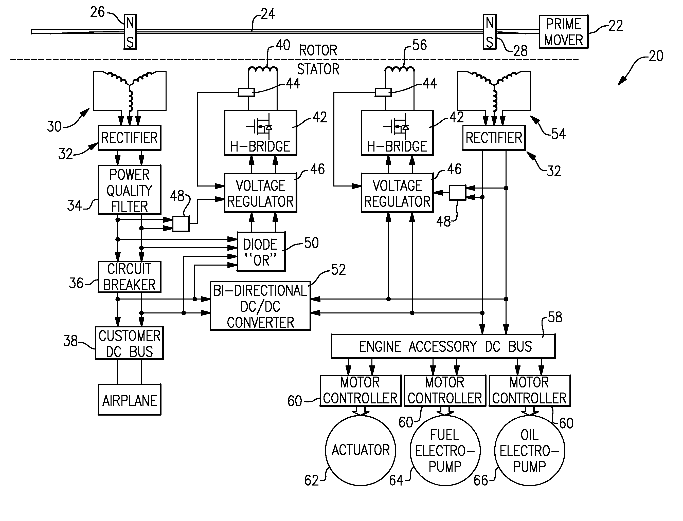
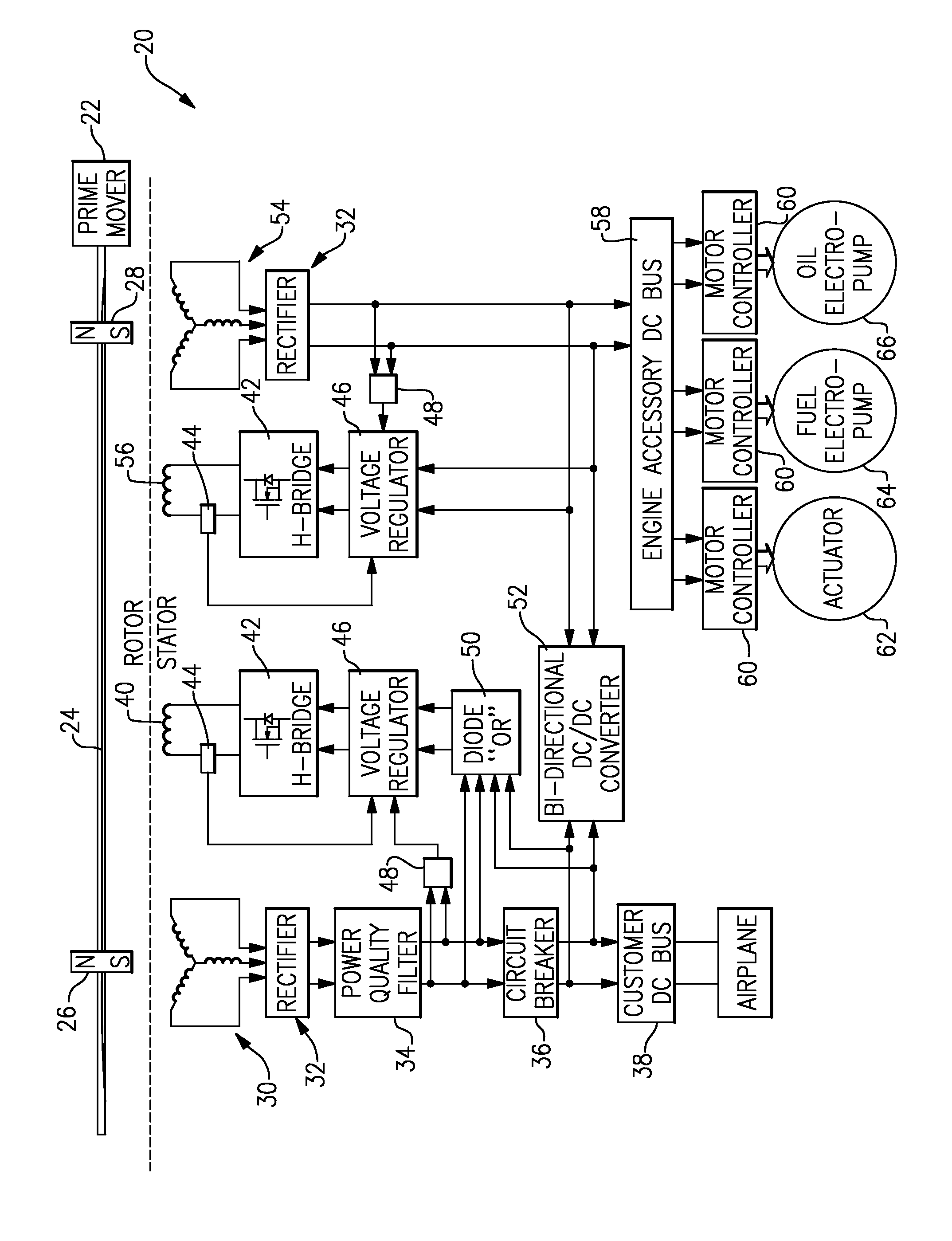
[0009]A generator and electrical supply system 20 for use, such as on an airplane, includes a prime mover 22, which may be a gas turbine engine. Prime mover 22 drives a shaft 24. Permanent magnets 26 and 28 rotate with the shaft 24. A three-phase stator winding 30 is positioned adjacent the magnet 26, and supplies current through a rectifier 32, a filter 34, a circuit breaker 36, and to a customer DC bus 38. The customer DC bus 38 may supply electrical power such as to various systems and components on an airplane.

[0010]A control winding 40 is provided to control the current and voltage supplied to the bus 38. A current sensor 44 provides sensed current to a voltage regulator 46, and a voltage sensor 48 does the same. An H-bridge 42 is associated with this control circuitry. A diode OR gate 50 is associated into the circuitry to enable control power to the voltage regulator from either power quality filter 34, or from bi-directional dc / dc converter 52.

[0011]A bidirectional DC / DC con...


PUM


Abstract

A generator and associated power supply system has a prime mover for driving a shaft to rotate. A pair of permanent magnets is associated with the rotating shaft. A first stator winding is associated with a first of said permanent magnets, with a customer DC bus for providing a first relatively low voltage to the customer DC bus. A second of said permanent magnets is associated with a second stator winding, and an engine accessory DC bus. The engine accessory DC bus provides power to a motor controller and associated accessory motors associated with the prime mover. The engine accessory DC bus is provided with a second relatively high voltage from the second stator winding.

Description

BACKGROUND OF THE INVENTION[0001]This application relates to an electrical generation system wherein separate permanent magnet generators and associated buses are provided for a load, and for accessories associated with the generator.[0002]Generators for generating electricity are known. One common generator is provided by a gas turbine engine, such as on an aircraft.[0003]Recently, an electrical system associated with a gas turbine engine has been developed to provide electricity to a DC bus for providing power to various components associated with an aircraft carrying the gas turbine engine. A separate bus is provided to provide power and control signals to pumps and other motors associated with the engine itself.[0004]One challenge with such a system is that the engine accessories tend to need increased voltage levels compared to the other components on the aircraft.[0005]Providing such distinct voltage levels has proved challenging, and has raised cost and weight, as well as har...

Claims


Application Information

Patent Timeline
Patent Type & Authority Patents(United States)
IPC IPC(8): H02P9/10
CPCH02J1/12H02P9/307H02P2101/30H02J2310/44
Inventor ROZMAN, GREGORY I.ROY, KEVIN P.
Owner HAMILTON SUNDSTRAND CORP
Learn More