Signal transmitting and receiving devices, systems, and method for multiplexing parallel data in a horizontal auxiliary data space
a technology of parallel data and transmitting and receiving devices, applied in the field of signal transmitting devices, signal transmitting methods, signal receiving devices, etc., can solve the problem of difficult multi-channel audio multi-channel with video data multiplexing, and achieve the effect of increasing the maximum number of multiplexes
- Summary
- Abstract
- Description
- Claims
- Application Information
AI Technical Summary
Benefits of technology
Problems solved by technology
Method used
Image

Examples
first embodiment
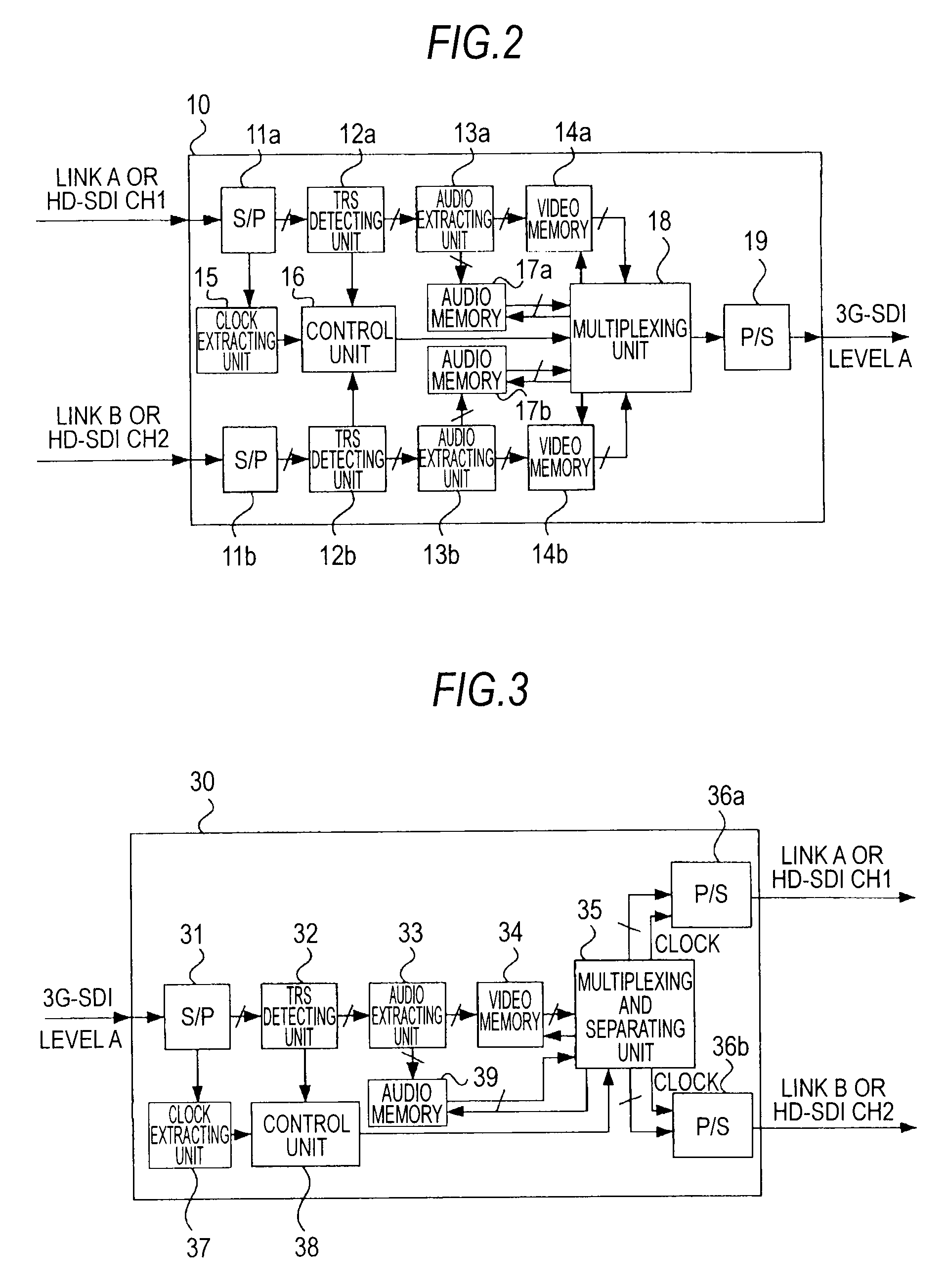
[0039]the present invention is explained below with reference to FIGS. 1 to 16. In an example explained in this embodiment, the present invention is applied to a signal transmitting device 10 and a CCU 2 that can transmit serial digital data obtained by multiplexing audio data with video data using a 3G-SDI.
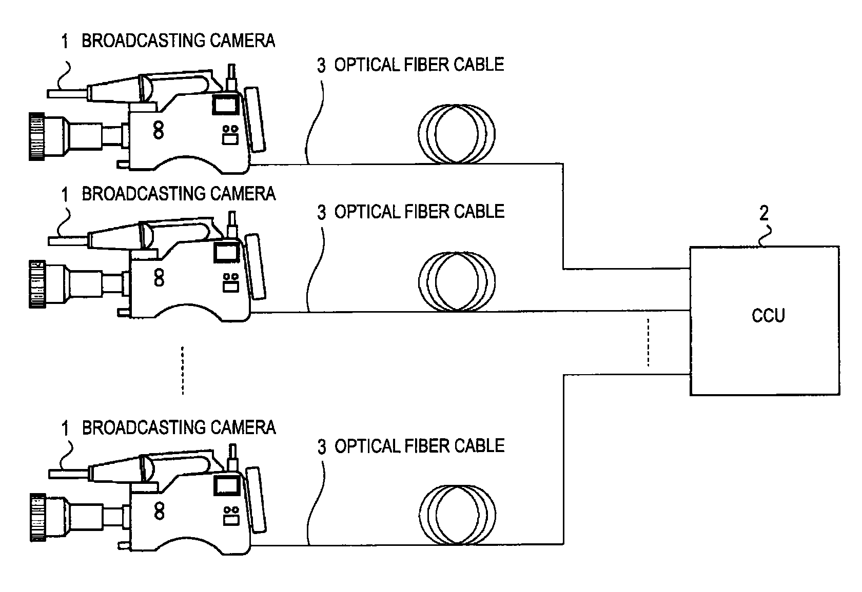
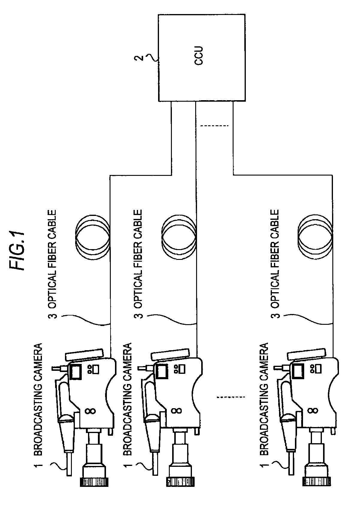
[0040]FIG. 1 is a diagram of an overall configuration of a camera transmission system for a television broadcasting station according to this embodiment. The camera transmission system includes plural broadcasting cameras 1 and a CCU (camera control unit) 2. The broadcasting cameras 1 are connected to the CCU 2 by optical fiber cables 3.
[0041]The broadcasting cameras 1 have the same configuration and generate an m-bit quantized signal (m is 10 or 12) for broadcast as a 1080 P signal or a 1080I / 4:4:4 signal. The broadcasting cameras 1 include signal transmitting devices 10 that transmit a signal in a level A of a 3G-SDI format. When the m-bit quantized signal adopted by the broadc...
second embodiment
[0148]the present invention is explained with reference to FIGS. 17 and 18. However, in FIGS. 17 and 18, components corresponding to those shown in FIGS. 2 and 3 referred to in the first embodiment are denoted by the same reference numerals and signs and detailed explanation of the components is omitted.
[0149]FIG. 17 is a diagram of an internal configuration example of a signal transmitting device 21 according to the second embodiment. The signal transmitting device 21 is input with N channels (ch1 to chN) of LVDS signals in a differential transmission system multiplexed with audio data. The signal transmitting device 21 includes, according to the number of channels, n S / P converting units 11a to 11n, n word detecting units 22a to 22n that detect word synchronous signals from parallel data, n audio extracting units 13a to 13n, and n video memories 14a to 14n.
[0150]An operation example of the signal transmitting device 21 is explained.
[0151]When an input signal is a multi-channel LV...
third embodiment
[0154]FIG. 19 is a diagram of an internal configuration example of a signal transmitting device 22 according to the present invention.
[0155]The signal transmitting device 22 is input with N channels (ch1 to chN) of serial signals of plural channels in the differential transmission system such as LVDSs in the differential transmission system multiplexed with audio data. The signal transmitting device 21 includes an audio extracting unit 23 that extracts input audio data and stores the audio data in an audio memory 17c. The signal transmitting device 22 includes, according to the number of channels, the n S / P converting units 11a to 11n, the n word detecting units 22a to 22n that detect word synchronous signals from parallel data, and the n video memories 14a to 14n.
[0156]An operation example of the signal transmitting device 22 is explained.
[0157]When an input signal is not multiplexed with audio data and input from the outside to the signal transmitting device 22 in a data format s...
PUM
 Abstract
Description
Claims
Application Information
 - R&D
- Intellectual Property
- Life Sciences
- Materials
- Tech Scout
- Unparalleled Data Quality
- Higher Quality Content
- 60% Fewer Hallucinations
Browse by: Latest US Patents, China's latest patents, Technical Efficacy Thesaurus, Application Domain, Technology Topic, Popular Technical Reports.
© 2025 PatSnap. All rights reserved.Legal|Privacy policy|Modern Slavery Act Transparency Statement|Sitemap|About US| Contact US: help@patsnap.com