

Adjustable bases for sighting devices
a technology of telescopic sights and mounting systems, which is applied in the direction of sighting devices, butts, weapons, etc., can solve the problems of reducing accuracy, rear lens refraction distortion, and three major parts of a telescopic sight that are far more complex than the casual user might imagine, so as to achieve the effect of measuring the long-term durability of high-dollar glass
- Summary
- Abstract
- Description
- Claims
- Application Information
AI Technical Summary
Benefits of technology
Problems solved by technology
Method used
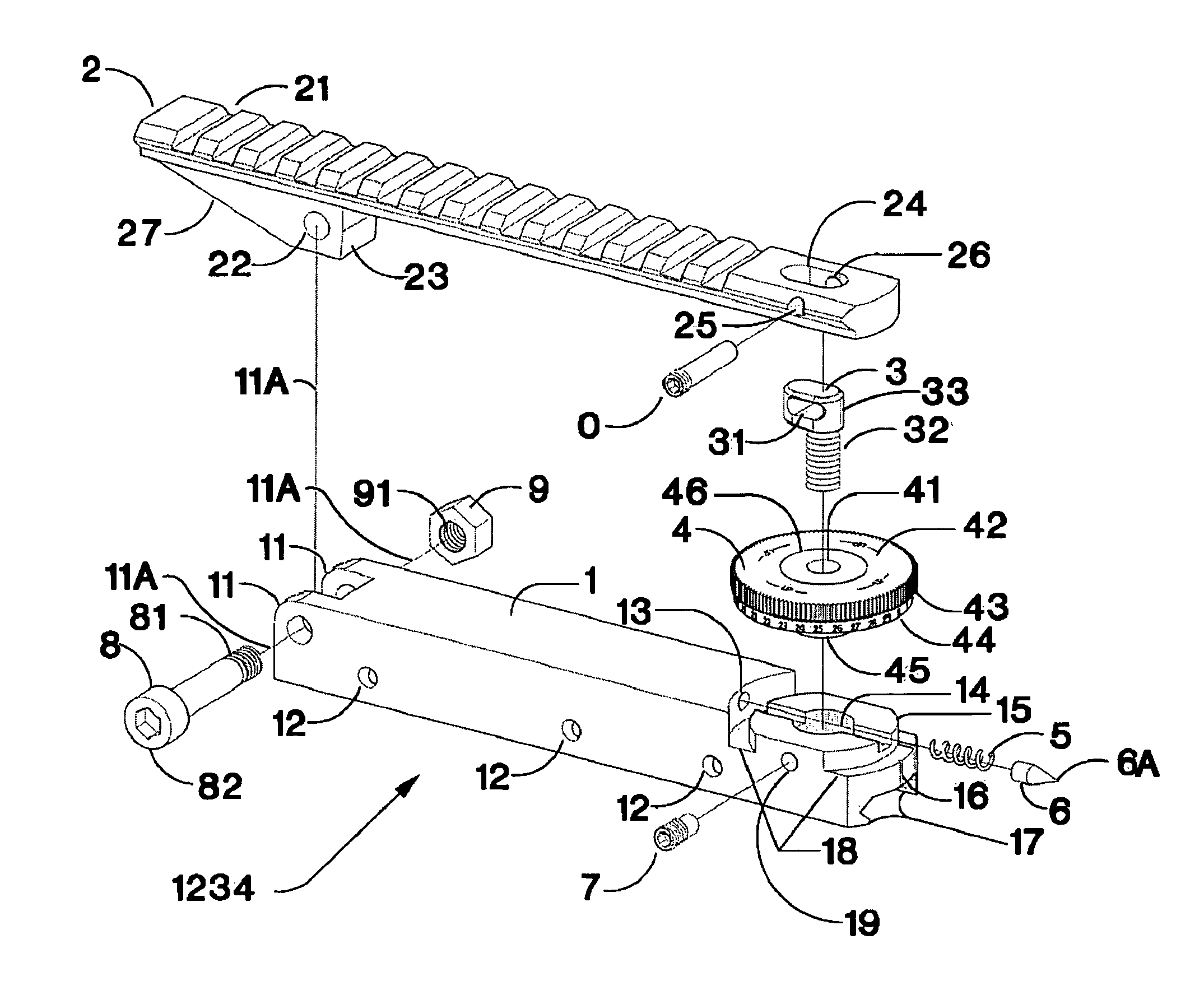
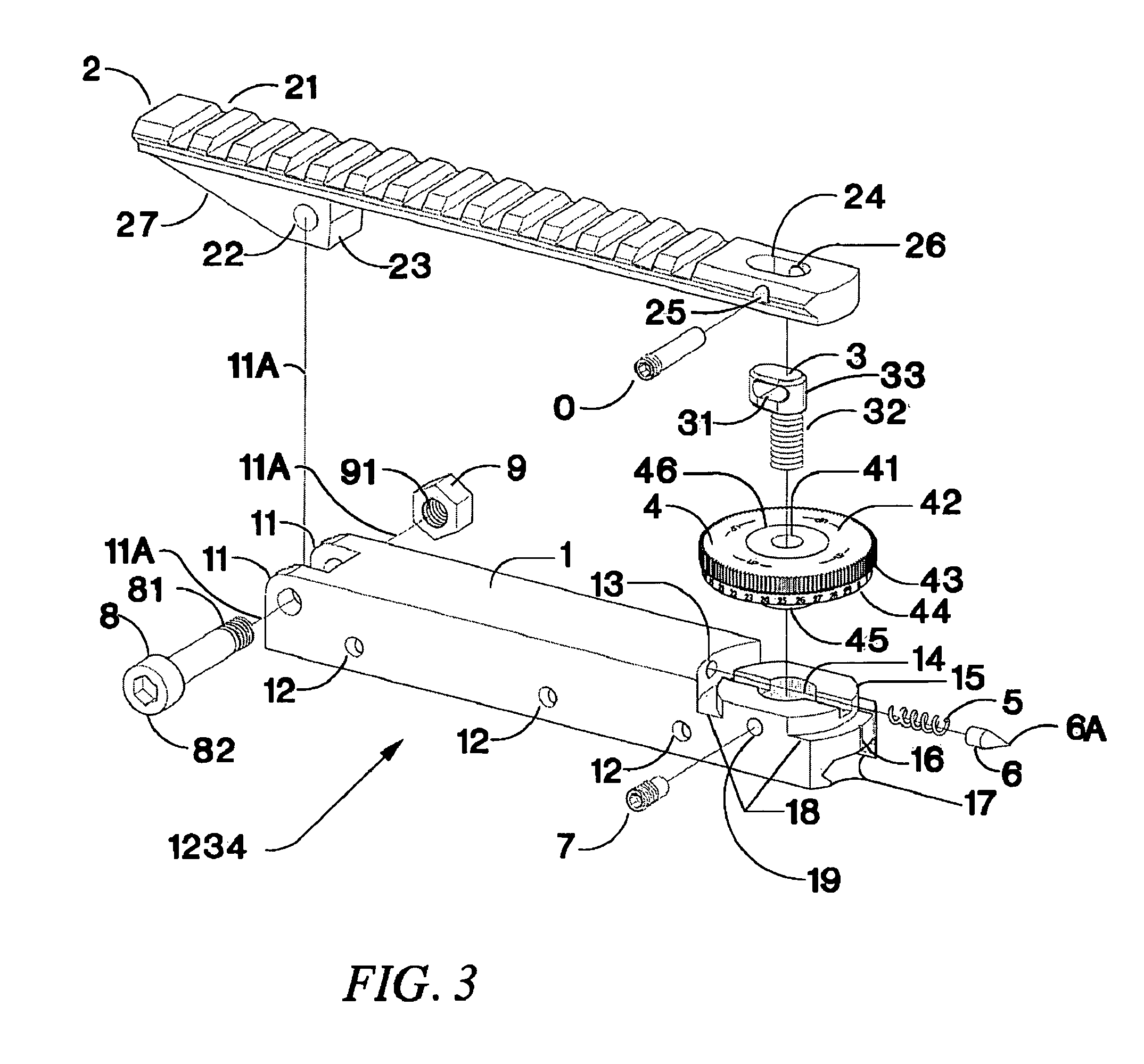
Image

Examples
Embodiment Construction
[0047]The following description of various embodiments uses a terrestrial frame of reference in which “top” and “bottom” or “upper” and “lower” refer to the portions of an article facing away from or toward the force of gravity when arranged in what would be considered an upright position for normal use. Also, with regard to typical small arms and other hand-held weapons, the terms “breech” or “rear” and “muzzle” or “front” can be used to refer to opposite ends of the weapon. The expression “A and / or B” is used in a conventional sense, meaning that A, B or both A and B may be present.
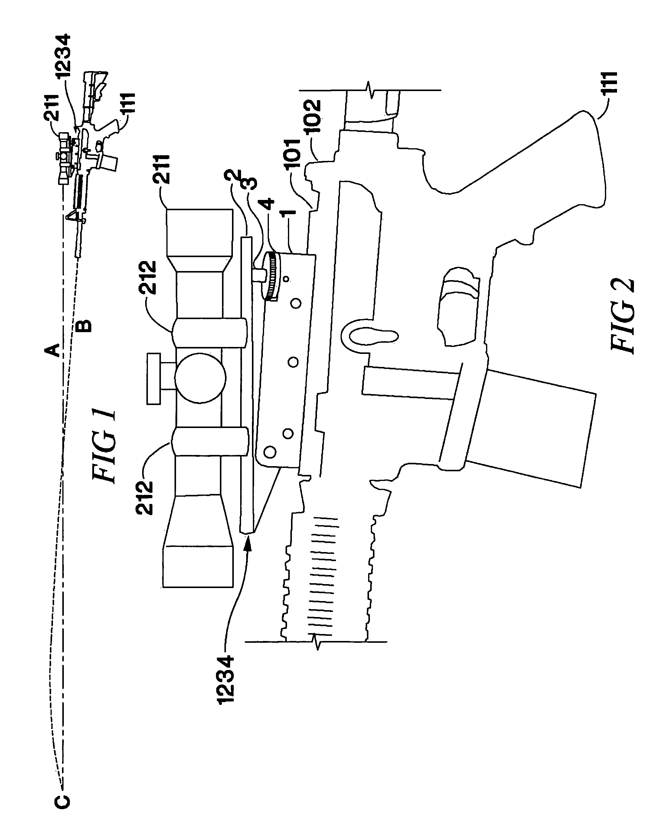
[0048]FIG. 1 shows a rifle 10 (of the AR-15 or M-16 type) upon which a telescopic sight 11 has been mounted with an embodiment 1234 of the adjustable scope mount. The angle between the scope and the barrel axis has been adjusted so that the line of sight A and the ballistic trajectory B of the bullet meet at the distant target C.
[0049]FIG. 2 shows the attachment of scope 211 to rifle 111 using scope rin...
PUM
 Abstract
Description
Claims
Application Information