Adjustable conveyor assembly for a combine

a conveyor assembly and combine technology, applied in the field of combine harvesting, can solve the problems of not always feasible distances, waste of time, and not without significant disadvantages, and achieve the effect of superior combine operation, quick, convenient and effectiv

Inactive Publication Date: 2012-08-14
LATIMER LESLIE B
View PDF24 Cites 32 Cited by
  • Summary
  • Abstract
  • Description
  • Claims
  • Application Information

AI Technical Summary

Benefits of technology

[0006]The inventor recognized these problems and has addressed this need by developing an attachable adjustable conveyor belt system for a combine that provides for vastly superior operation of a combine in a manner which is quick, easy, and effective without the multiple disadvantages of present auger-based systems. The inventor has thus realized the advantages and benefits of providing the adjustable conveyor assembly attachable to the combine having an elongated auger shaft disposed within a vertical auger housing of the combine. The shaft has a lower end mechanically coupled to an auger drive of the combine to move the harvested material upwardly. An enclosed fixed conveyor section is fastened to an upper end of the vertical auger housing to receive the harvested material and includes a conveyor roller track disposed on a lower edge of each opposing side. An adjustable conveyor section is slidingly attached to the fixed conveyor section and has a plurality of conveyor rollers protruding outwardly from opposing sides which are rotatably movable within the conveyor roller track as the adjustable conveyor section moves relative to the fixed conveyor section. A rack-and-pinion gear mechanism is provided between the fixed and adjustably conveyor sections for linearly moving the adjustable conveyor section relative to the fixed conveyor section. A rack-and-pinion drive motor is in mechanical communication with the rack-and-pinion gear mechanism to provide the driving force to the adjustable conveyor section. A conveyor belt drive roller is rotatably attached of the fixed conveyor section and a conveyor belt drive motor in mechanical communication with the conveyor belt drive roller to drive a single serpentine conveyor belt. A plurality of idle rollers is rotatably attached to ends of the fixed conveyor section and the adjustable conveyor section. The conveyor belt extends around the conveyor drive roller and the plurality of idle rollers, wherein the conveyor belt extends as the distal end of the adjustable conveyor section extends and retracts as the distal end of the adjustable conveyor retracts by movement at least one of the plurality of idle rollers. A plurality of support rollers is rotatably attached along both the fixed conveyor section and the adjustable conveyor section to support the conveyor belt between the plurality of idle rollers.

Problems solved by technology

While these systems have worked well for many years, they are not without significant disadvantages.
As one can imagine, such distances are not always feasible based upon crop layout, field obstructions, and the like.
This requires much jockeying of the combine to allow for a wide path, thus resulting in wasted time.
Secondly, auger-based systems are difficult to fully empty due to their design and reliance upon other systems associated with the combine.
This makes it exceedingly difficult to start up a full auger again in the future due to internal friction forces caused by the grain residing along the auger threading.
Various attempts have been made to provide improved combines and grain unloading devices; however, while these attempts may achieve their purported objective each suffers from one or more disadvantage or deficiency related to design or utilization.
Particularly, none of these attempts effectively address the decreased production efficiency and operational control limitations provided by conventional mechanical harvesting techniques.

Method used


Image

  • Adjustable conveyor assembly for a combine
  • Adjustable conveyor assembly for a combine
  • Adjustable conveyor assembly for a combine

Examples


Embodiment Construction

[0021]In accordance with the invention, the best mode is presented in terms of a preferred embodiment, herein depicted within FIGS. 1 through 8. However, the disclosure is not limited to a single described embodiment and a person skilled in the art will appreciate that many other embodiments are possible without deviating from the basic concept of the disclosure and that any such work around will also fall under its scope. It is envisioned that other styles and configurations can be easily incorporated into the teachings of the present disclosure, and only one particular configuration may be shown and described for purposes of clarity and disclosure and not by way of limitation of scope.

[0022]The terms “a” and “an” herein do not denote a limitation of quantity, but rather denote the presence of at least one of the referenced items.

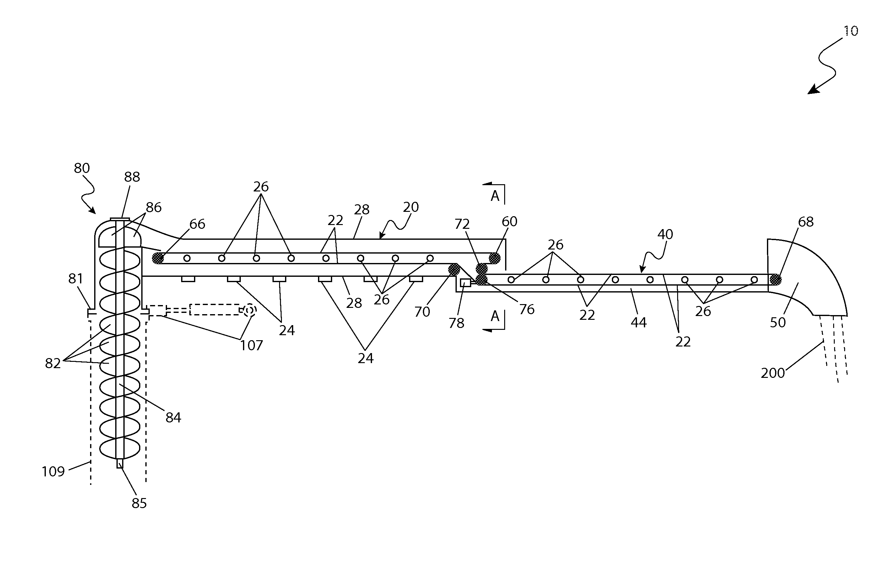
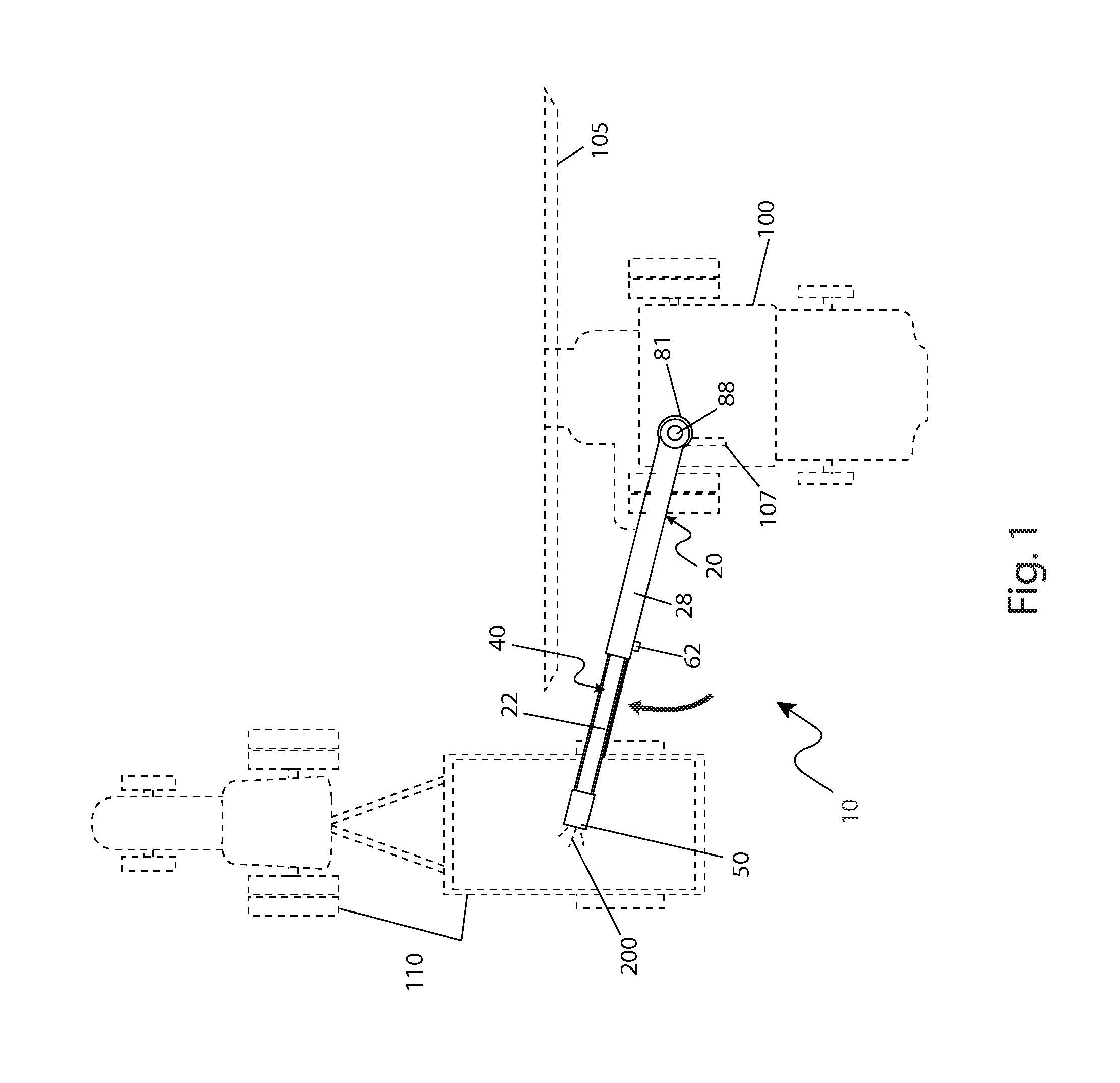
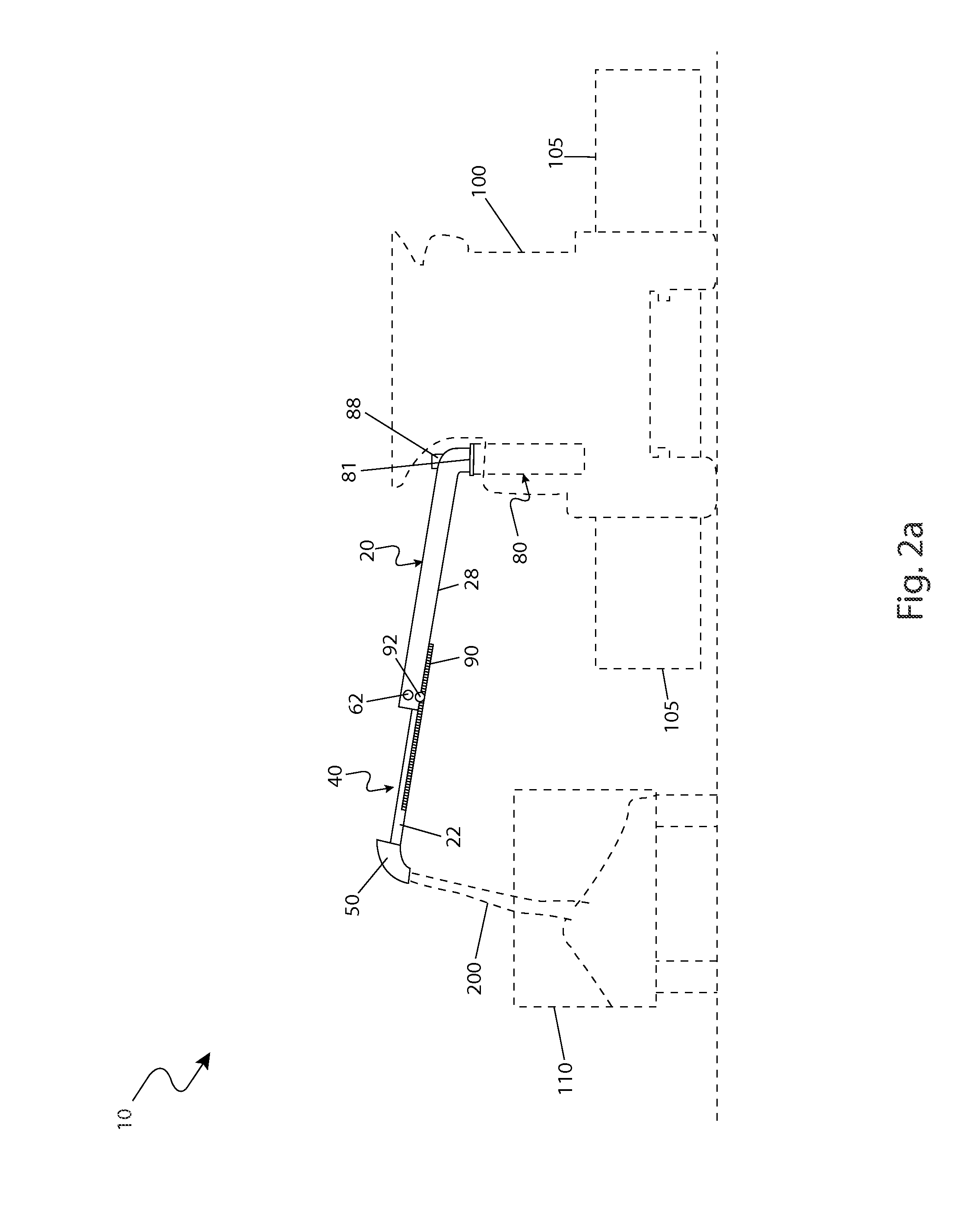
[0023]Referring now to FIGS. 1 through 8, depicting an adjustable conveyor assembly (herein described as an “apparatus”) 10 attachable to and for use with...


PUM


Abstract

An adjustable conveyor assembly attachable to a harvesting combine includes a pair of telescoping conveyor sections providing a length adjustable conveyor for the conveyance of harvested materials being unloaded from a combine bin. The conveyors include a hydraulically motorized extension and conveyor belt drive as well as associated user controls. The conveyor is controlled by a control module located within the combine cab which provides user interface and programmable functions.

Description

RELATED APPLICATIONS[0001]The present invention was first described in a notarized Official Record of Invention on Feb. 23, 2010, that is on file at the offices of Montgomery Patent and Design, LLC, the entire disclosures of which are incorporated herein by reference.FIELD OF THE INVENTION[0002]The present invention relates generally to harvesting combines, and in particular, to an adjustable conveyor belt attachable to a combine having a telescoping conveyor assembly for unloading harvested material from a combine bin.BACKGROUND OF THE INVENTION[0003]The field of agriculture relies upon many different machines in order to provide efficiency and lower the cost of food production. Perhaps the most well-known of these machines is the combine, which is used to harvest various grains. After the grains are harvested they must be emptied from the combine bin to various offloading vehicles such as trailers. The conventional method of emptying the conveyor bid relies upon the use of an auge...

Claims


Application Information

Patent Timeline
Patent Type & Authority Patents(United States)
IPC IPC(8): A01D17/02A01F12/46
CPCA01D41/1217A01F12/46
Inventor LATIMER, LESLIE B.
Owner LATIMER LESLIE B
Why Eureka
Try Eureka