
Micro coaxial cable for high bending performance

a coaxial cable and micro-coaxial technology, applied in the field of coaxial cables, can solve the problems of insignificant signal leakage between the coaxial cables, and no development progress for providing long-term uniform reliability, and achieve the effect of high bending performan

Active Publication Date: 2012-08-14
HITACHI METALS LTD
View PDF19 Cites 220 Cited by
  • Summary
  • Abstract
  • Description
  • Claims
  • Application Information

AI Technical Summary

Benefits of technology

[0009]The present invention was suggested to solve the above-mentioned problem, and an object of the present invention is to provide a micro coaxial cable with a high bending performance for providing a long-term uniform reliability in a severe environment such as bending or rotation.
[0017]And, the micro coaxial cable of the present invention may further comprise an over-foaming barrier layer formed between the insulating layer and the helical winding conductor and configured to prevent over-foaming of the insulating layer, so that foam cells are formed uniformly in the insulating layer.

Problems solved by technology

And, even when a plurality of coaxial cables are received in a single cable, signal leakage between the coaxial cables is insignificant.
However, as mentioned above, the conventional coaxial cable has been developed to enhance transmission speed or reduce the loss of transmission energy, but did not show any development progress for providing a long-term uniform reliability in a severe environment such as bending or rotation.

Method used


Image

  • Micro coaxial cable for high bending performance
  • Micro coaxial cable for high bending performance
  • Micro coaxial cable for high bending performance

Examples


Embodiment Construction

[0022]Hereinafter, preferred embodiments of the present invention will be described in detail with reference to the accompanying drawings. Prior to the description, it should be understood that the terms used in the specification and the appended claims should not be construed as limited to general and dictionary meanings, but interpreted based on the meanings and concepts corresponding to technical aspects of the present invention on the basis of the principle that the inventor is allowed to define terms appropriately for the best explanation. Therefore, the description proposed herein is just a preferable example for the purpose of illustrations only, not intended to limit the scope of the invention, so it should be understood that other equivalents and modifications could be made thereto without departing from the spirit and scope of the invention. Hereinafter, a preferred embodiment of the present invention will be described in detail with reference to the accompanying drawings....


PUM

PropertyMeasurementUnit
elongationaaaaaaaaaa

Abstract

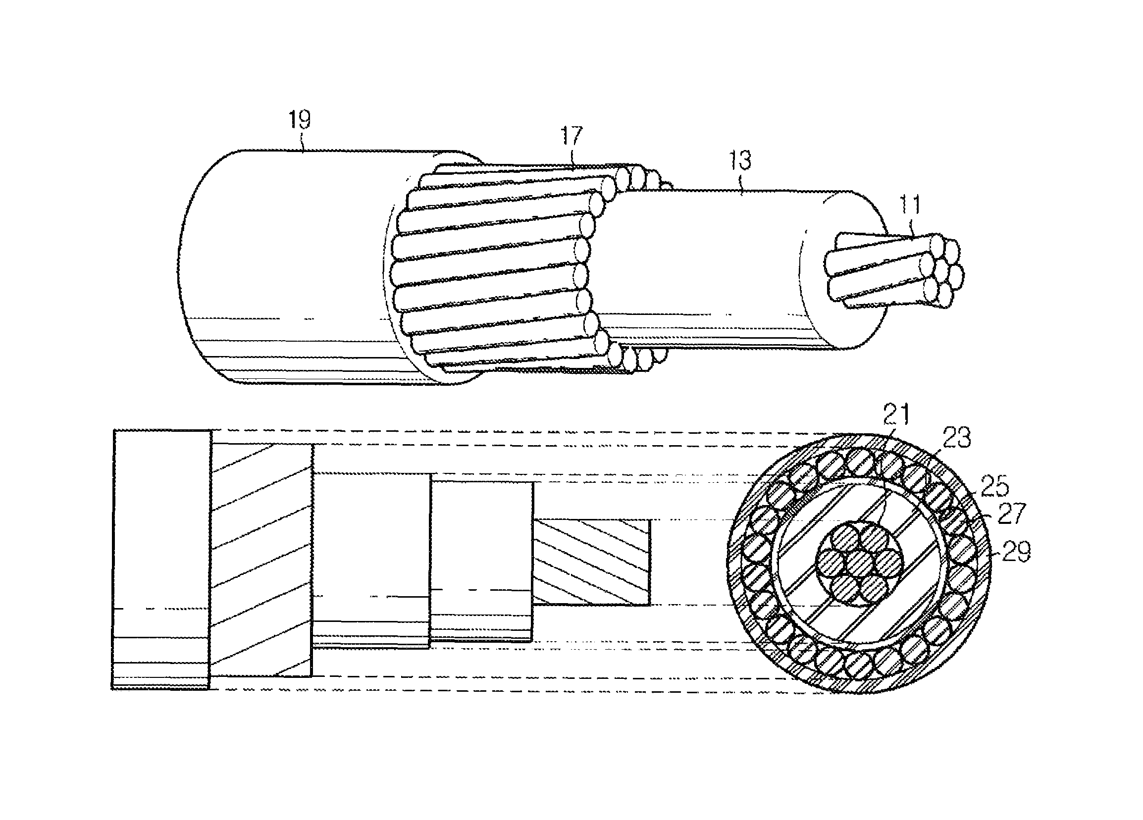
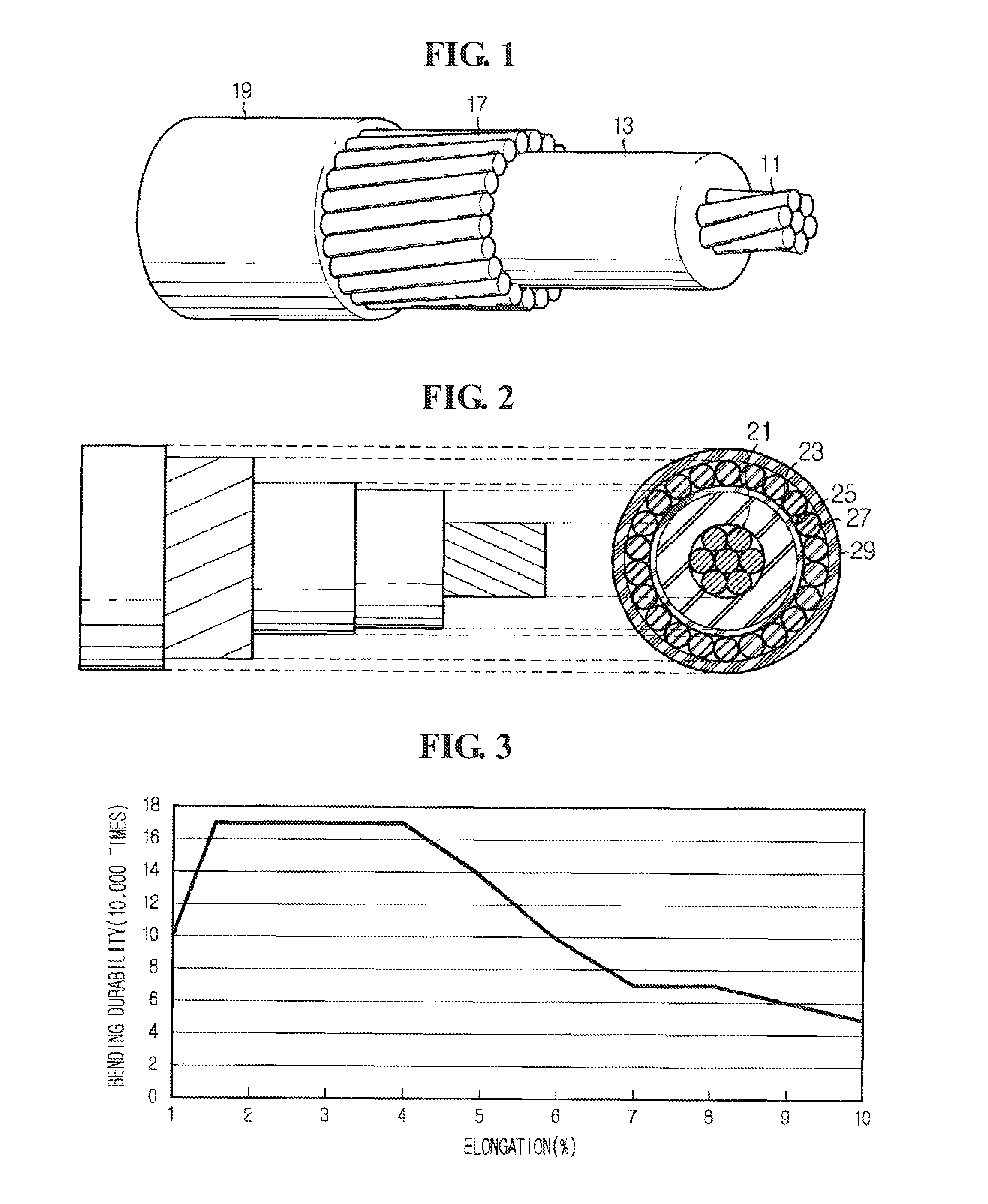
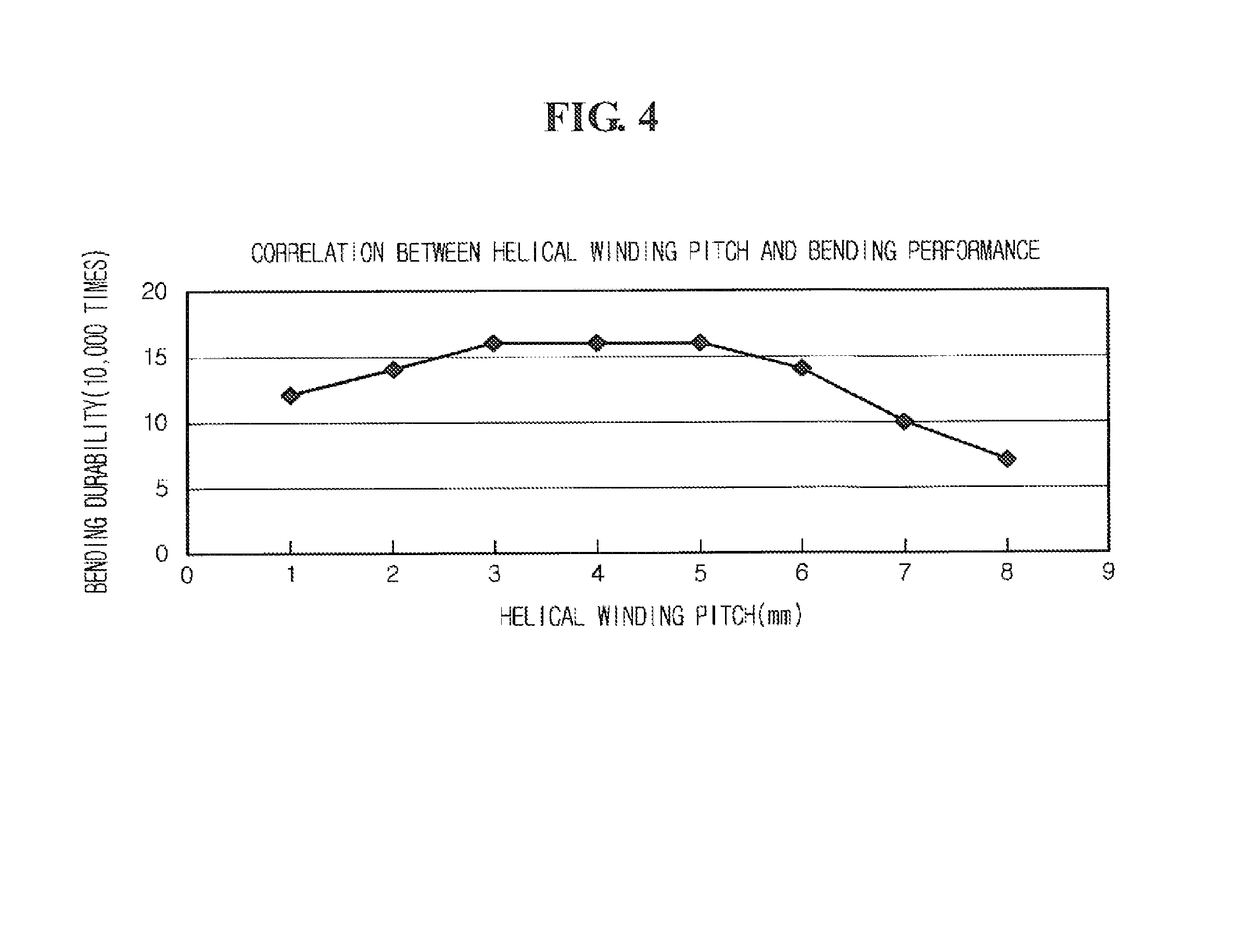
A micro coaxial cable with a high bending performance, having an inner conductor; an insulating layer configured to surround the inner conductor, and a helical winding conductor configured to surround the insulating layer and having an elongation of 1.5 to 4% and a pitch of 3.0 to 5.0 mm.

Description

CROSS REFERENCE TO PRIOR APPLICATIONS[0001]This application is a National Stage Patent Application of International Patent Application No. PCT / KR2007 / 005625 (filed on Nov. 8, 2007) under 35 U.S.C. 371, which claims priority to Korean Patent Application No. 10-2007-0012733 (filed on Feb. 7, 2007), which are both hereby incorporated by reference in their entirety.TECHNICAL FIELD[0002]The present invention relates to a coaxial cable, in particular, to a micro coaxial cable.BACKGROUND ART[0003]Generally, a coaxial cable is a transmission line comprising an inner conductor for signal transmission and a shield layer formed on a concentric axis of the inner conductor, when the coaxial cable is viewed in cross section, the inner conductor and the shield layer form concentric circles, and an insulating layer having a dieletric property is formed between the inner conductor and the shield layer.[0004]The coaxial cable has been developed as various products according to size and kind, and due ...

Claims


Application Information

Patent Timeline
Patent Type & Authority Patents(United States)
IPC IPC(8): H01B7/00
CPCH01B11/1821H01B1/02H01B11/18H01B11/1808H01B11/1878H01B11/1895
Inventor PARK, CHAN-YONGSEO, IL-GUNNAM, GI-JOONPARK, JUNG-WONKIM, IN-HALEE, GUN-JOOKIM, JUNE-SUN
Owner HITACHI METALS LTD
Learn More