
Wind turbine generator

a wind turbine generator and wind turbine technology, applied in the direction of electric generator control, machines/engines, mechanical equipment, etc., can solve the problems of increasing cost and increasing machining costs, and achieve the effect of reducing the weight of the nacelle, reducing the driving torque required by the yaw motor, and reducing the cost of machining a gear having a large diameter

Inactive Publication Date: 2012-08-14
MITSUBISHI HEAVY IND LTD
View PDF7 Cites 9 Cited by
  • Summary
  • Abstract
  • Description
  • Claims
  • Application Information

AI Technical Summary

Benefits of technology

The present invention provides a wind turbine generator that does not require a gear with a large diameter in the yaw drive device, which reduces the cost of machining and eliminates the risk of leaking grease. The yaw drive device includes a yaw motor fixedly provided on the nacelle base plate or on the fixed-side support member provided in the vicinity of the upper end of the tower, with the output shaft and the nacelle or the fixed-side support member coupled by a coupling shaft with couplings provided at both ends thereof. This eliminates the need for a gear with a large diameter and reduces the weight of the nacelle. The invention also reduces the driving torque required by the yaw motor and increases the efficiency of the yaw system.

Problems solved by technology

In other words, the ring gear 16 needs to be manufactured to have a diameter approximately identical to the inner diameter of the upper end portion of the tower 2 whose diameter is increased when the nacelle 3 is increased in size, and therefore, there is a problem in that the machining cost increases.
Further, in the above-described conventional structure, in order to precisely control backlash at the engagement portion of the drive gear 14 and the ring gear 16, precise machining of the nacelle base plate 12, which is a fixed side, is also required, thus increasing the cost.

Method used


Image

  • Wind turbine generator
  • Wind turbine generator
  • Wind turbine generator

Examples


Embodiment Construction

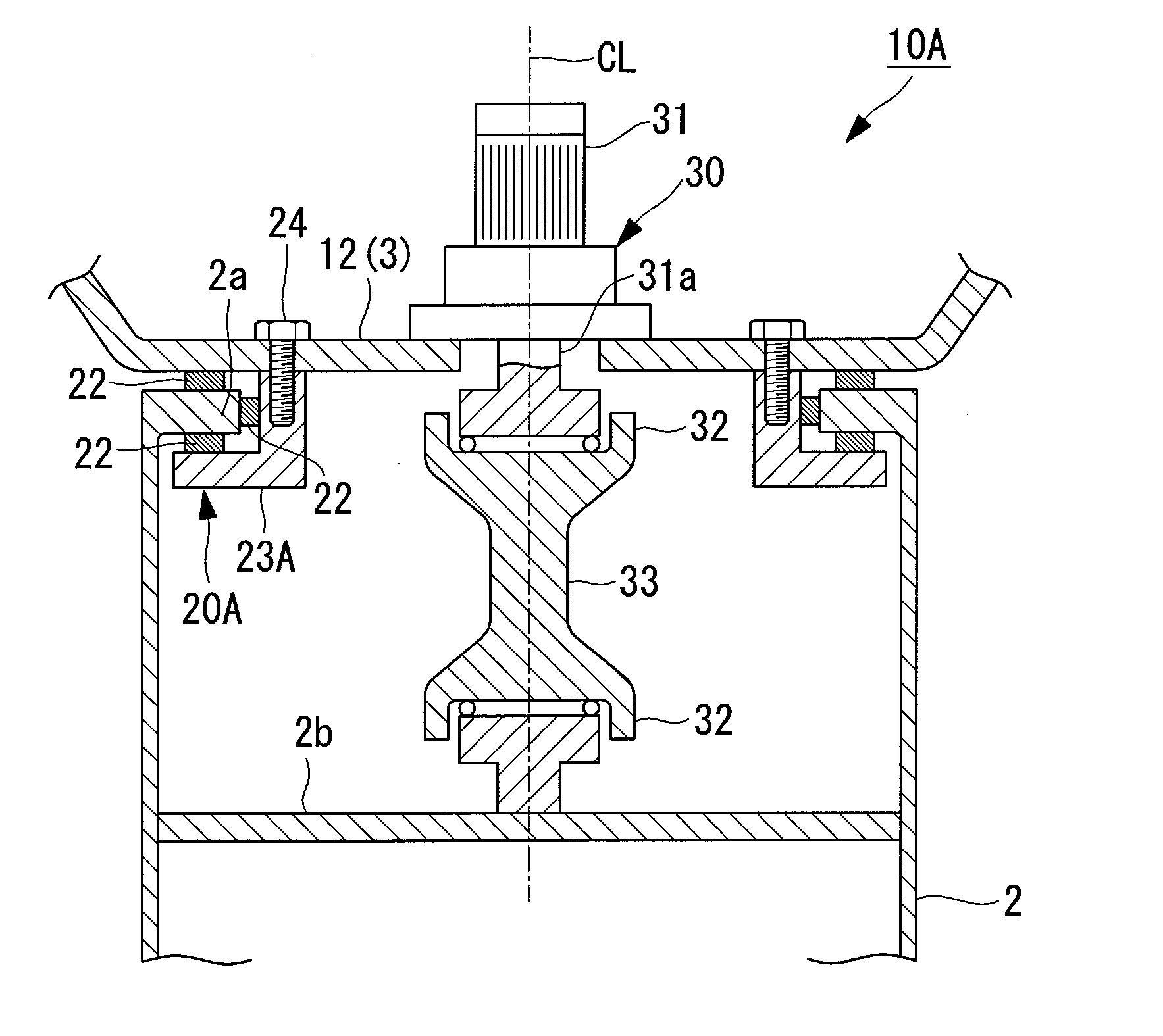
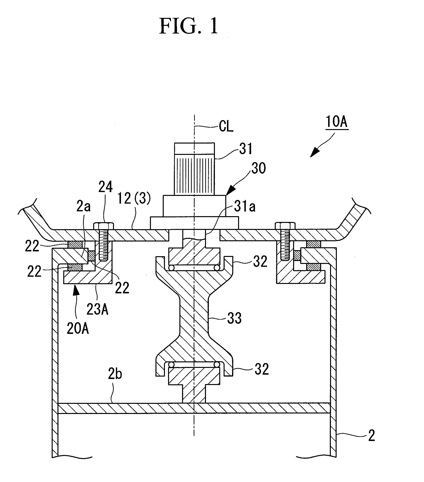
[0049]A wind turbine generator according to an embodiment of the present invention will be described below with reference to FIGS. 1 and 2.

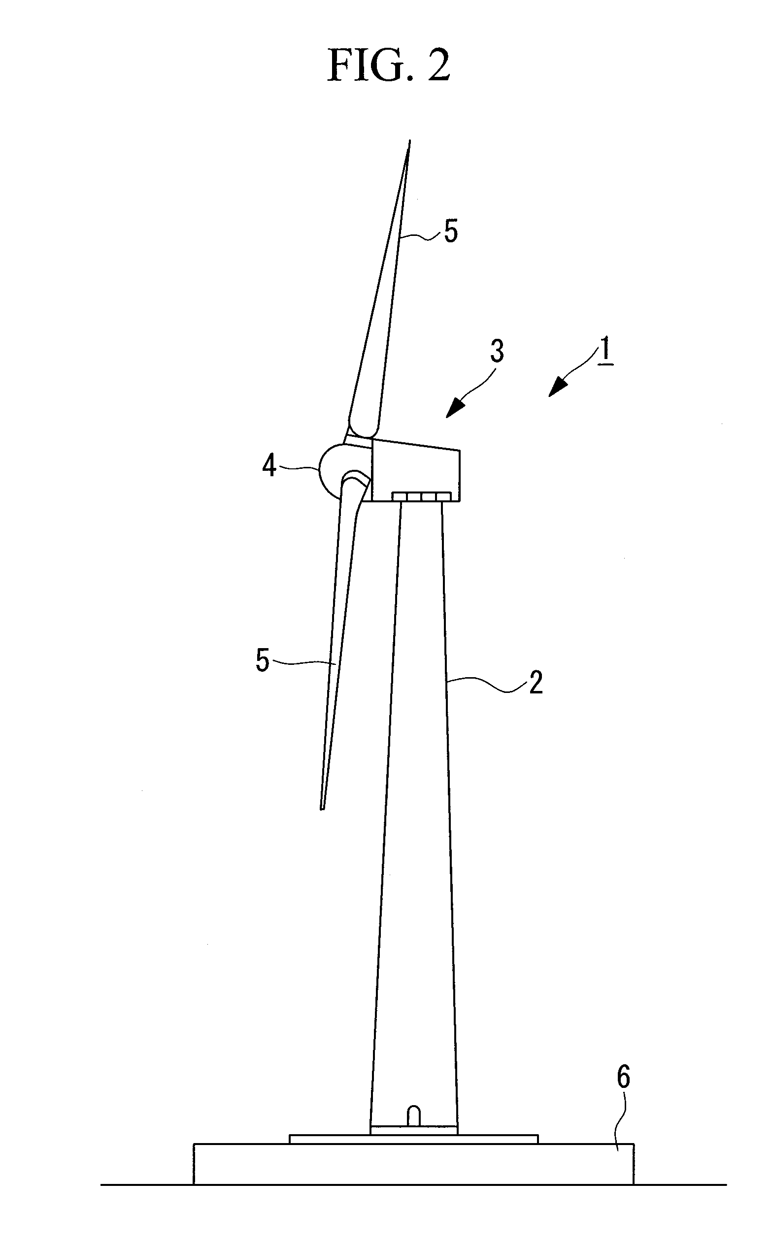
[0050]A wind turbine generator 1 shown in FIG. 2 includes a tower 2 provided upright on a foundation 6, a nacelle 3 provided at the upper end of the tower 2, and a rotor head 4 which is supported so as to be able to rotate about a substantially horizontal rotary axis and which is provided on the nacelle 3.

[0051]A plurality of (for example, three) wind-turbine rotor blades 5 are radially attached to the rotor head 4 around its rotary axis. Thus, the force of wind blowing against the wind-turbine rotor blades 5 in a direction of the rotary axis of the rotor head 4 is converted into power which rotates the rotor head 4 about the rotary axis.

[0052]The wind turbine generator 1 includes a yaw system which revolves the nacelle 3 located at the upper end of the tower 2. The yaw system is a device which turns the nacelle 3 in the optimum direction dependi...


PUM


Abstract

A wind turbine generator is provided in which a gear having a large diameter is not required in a yaw drive device (30) of a yaw system (10A). The yaw drive device (30) of the yaw system (10A), which revolves a nacelle (3) depending on the wind direction, includes a electric motor (31) which is fixedly provided on a nacelle base plate (12), with an output shaft (31a) substantially aligned with a pivot of the nacelle (3). The output shaft (31a) and a fixed-side support member (2b) provided in the vicinity of an upper end of the tower (2) are coupled by a coupling shaft (33) having couplings (32) provided at both ends thereof.

Description

CROSS-REFERENCE TO RELATED APPLICATIONS[0001]The present Application is based on International Application No. PCT / JP2008 / 060716, filed on Jun. 11, 2008, and priority is hereby claimed under 35 USC §119 based on this application. This application is hereby incorporated by reference in its entirety into the present application.TECHNICAL FIELD[0002]The present invention relates to wind turbine generators having a yaw system which revolves the nacelle (wind-turbine main body) depending on the wind direction.BACKGROUND ART[0003]Wind turbine generators, in which a wind turbine is rotated by the force of wind and rotational movement thereof is transferred to a generator to generate electricity, are conventionally provided with a yaw system which revolves (turns) a nacelle depending on the wind direction.[0004]The conventional yaw system includes a yaw drive device, a yaw slewing ring, and a yaw brake. Main components are disposed in the nacelle. Specifically, the nacelle, which includes t...

Claims


Application Information

Patent Timeline
Patent Type & Authority Patents(United States)
IPC IPC(8): F03D9/00
CPCF03D7/0204F03D11/0008F05B2260/90F05B2270/32F05B2270/321Y02E10/721Y02E10/722Y02E10/723Y02E10/726F03D80/70Y02E10/72F05B2240/50
Inventor NUMAJIRI, TOMOHIRO
Owner MITSUBISHI HEAVY IND LTD
Learn More