
High efficiency gas lighting device for an electric household appliance

a technology of gas lighting and electric household appliances, which is applied in the direction of household cooking appliances, combustion ignition, combustion process, etc., can solve the problems of not fully solving the technical problem of reaching a better electric efficiency of transformers, presenting relatively low electric efficiency, and large size of known gas lighting devices available today, so as to reduce size, reduce cost, and reduce the effect of siz

Active Publication Date: 2012-08-14
ITW IND COMPONENTS SRL
View PDF8 Cites 1 Cited by
  • Summary
  • Abstract
  • Description
  • Claims
  • Application Information

AI Technical Summary

Benefits of technology

This configuration significantly increases electric efficiency from less than 15% to over 50%, reduces device size and production costs, and simplifies assembly while maintaining the existing layout and assembly systems.

Problems solved by technology

Even though the known devices are entirely satisfactory from the technical point of view, they however display a relatively low electric efficiency which forces to use a relatively large amount of electric material for the construction thereof, in particular in the windings in order to achieve the required performance levels.
The known gas lighting devices available today thus present relatively high cost and large size.
In particular, the device known from EP-A-1469255 already displays many improvements from this point of view, in addition to brilliantly solving the specific problem of cost-effectively and simply equipping cooking ranges provided with either an even or an odd number of burners, but does not fully solve the technical problems of reaching a better electric efficiency of the transformer.
However, the simple carryover of such different transformer design to the field of electronic gas lighting devices is not possible because, on one hand, it is not at all suited to the current layout of gas lighting devices and would make the assembly thereof extremely complex and costly and, on the other hand, would be likely to increase the size, thus obtaining a result opposite to the desired one which consists in reducing the production and assembly costs and the size of the finished gas lighting device.

Method used


Image

  • High efficiency gas lighting device for an electric household appliance
  • High efficiency gas lighting device for an electric household appliance
  • High efficiency gas lighting device for an electric household appliance

Examples


Embodiment Construction

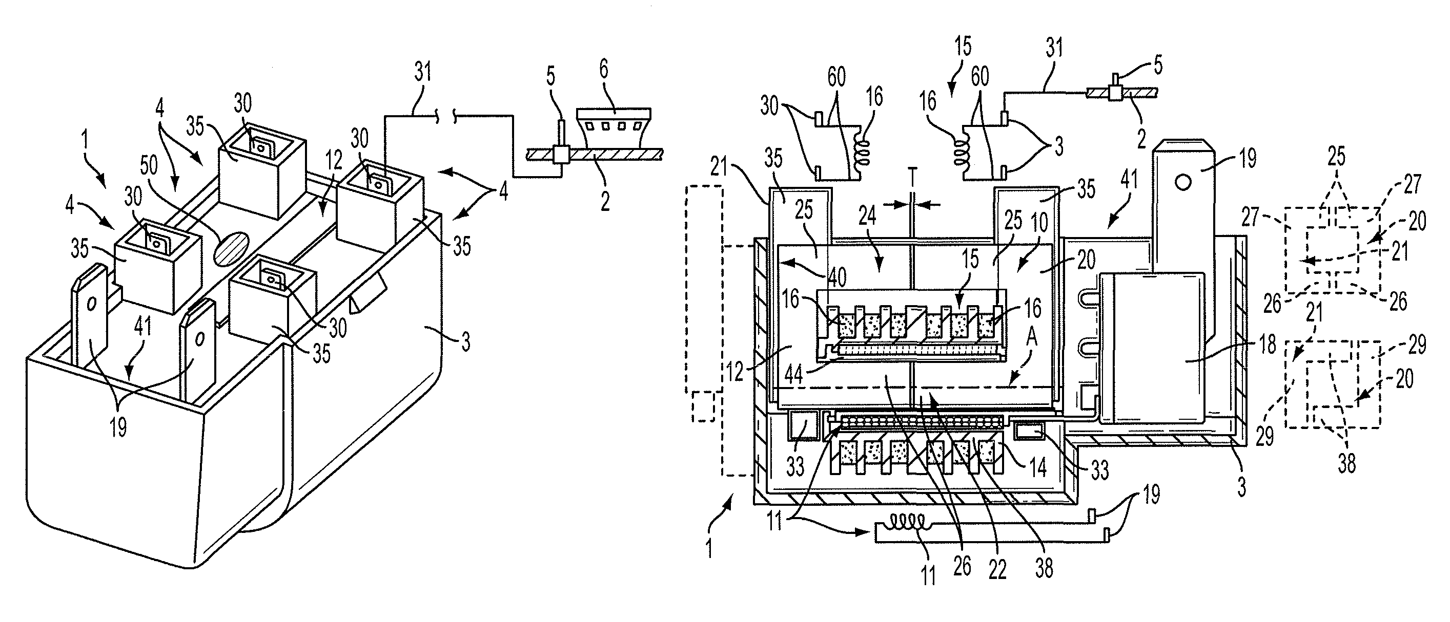
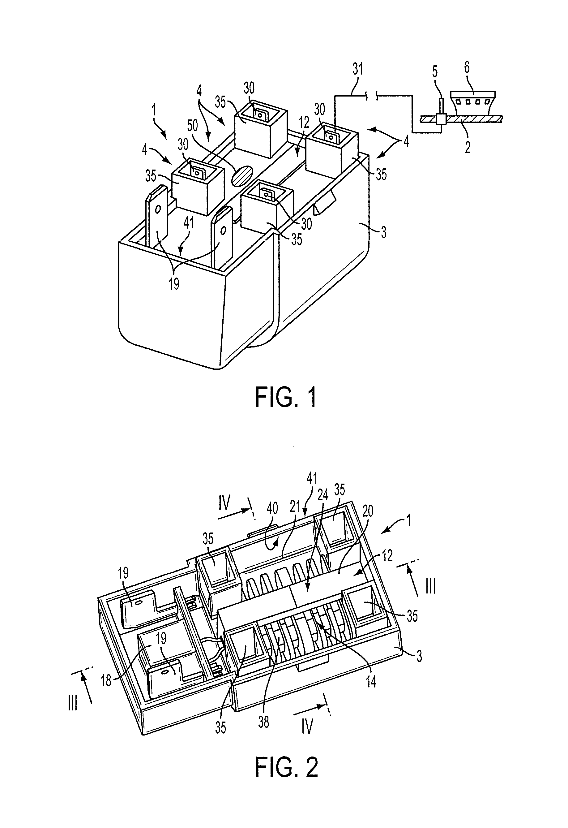
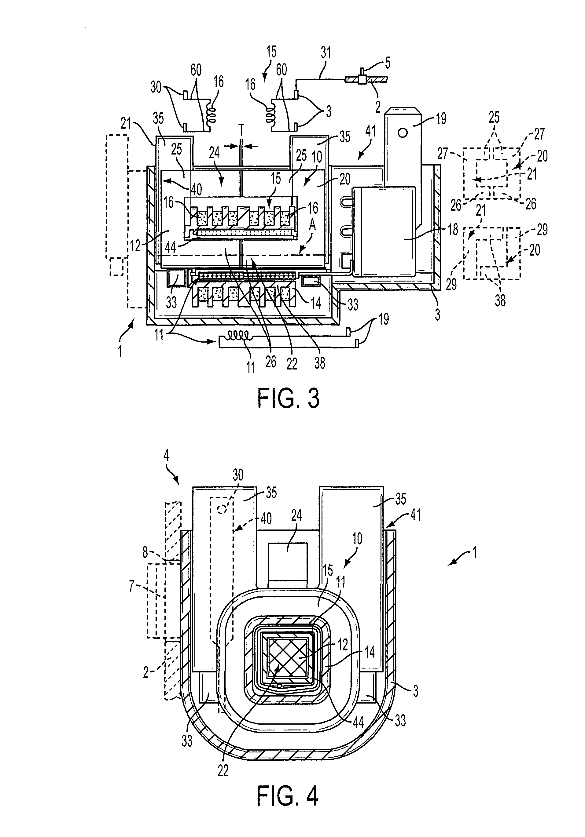
[0022]With reference to figures from 1 to 4, numeral 1 indicates as a whole a gas lighting device for an electric household appliance, which is a cooking range 2 (FIGS. 1, 3 and 4) in the non-limiting embodiment shown; the device 1 comprises a body 3 formed by an electrically insulating material, e.g. a synthetic plastic material such as polyamide, and carrying a plurality of high-voltage outputs 4 for the connection to spark generating means 5 of the cooking range 2; in the illustrated embodiment, the means 5 are spark plug electrodes integrally mounted on the cooking range 2 in known manner and each in proximity of a burner 6 (FIG. 1) of any known type adapted to equip the cooking range 2 and the body 3 is provided with known e.g. snapping, fastening means 7 (FIG. 4) to the cooking range 2, against which it may be mounted in use, in known manner (FIG. 4) at one or more fastening perforations 8 adapted to accommodate the fastening means 7.

[0023]The gas lighting device 1 further com...


PUM


Abstract

A gas lighting device including: a body formed by an electrically insulating material carrying a plurality of high-voltage outputs for the connection of spark generating means; a transformer accommodated in the body and including a primary winding wound around and carried by a ferromagnetic material core, a carrying element formed by an electrically insulating material and designed to contain the primary winding therein, and a secondary winding consisting of a plurality of coils externally carried by the carrying element, electrically insulated from the primary winding and essentially coaxial with the latter; the core is ring-shaped on a plane parallel to an axis (A) of the windings and consists of two half rings reciprocally coupled and arranged facing and closely adjacent to each other in the direction of the axis of the windings; a first circumferential portion of the ring-shaped core, formed by one or both of the half rings, is accommodated inside the carrying element so as to be surrounded by the windings, while a second circumferential portion of the core is formed parallel to the first and radially on the outside of the windings so as not to be surrounded by the same.

Description

RELATED APPLICATIONS[0001]The present application is based on International Application Number PCT / IB2008 / 000696 filed Mar. 25, 2008, and claims priority from Italian Application Number TO2007A000217 filed Mar. 26, 2007, the disclosures of which are hereby incorporated by reference herein in their entirety.TECHNICAL FIELD[0002]The present invention relates to a gas lighting device of the type intended to equip an electric household appliance, such as for example a cooking range, presenting high electric efficiency and, therefore, low consumptions and small size.BACKGROUND ART[0003]It is known that the electronic gas lighting devices currently present on the market, e.g. of the type described in EP-A-1469255 to the same Applicant, comprise a casing formed by electrically insulating material, in which high-voltage pulse generator means are arranged comprising electronic control means and a transformer provided with a primary winding and a secondary winding, the latter consisting of a ...

Claims


Application Information

Patent Timeline
Patent Type & Authority Patents(United States)
IPC IPC(8): F23Q3/00
CPCF23Q3/00H01F38/12F24C3/103Y02B40/166Y02B40/00
Inventor PIANEZZE, DANIELEALEARDI, MASSIMO
Owner ITW IND COMPONENTS SRL
Learn More