Combustion chamber

Inactive Publication Date: 2012-08-21
SIEMENS AG
View PDF16 Cites 12 Cited by
  • Summary
  • Abstract
  • Description
  • Claims
  • Application Information

AI Technical Summary

Benefits of technology

[0016]With an annular combustion chamber of a gas turbine which is equipped with what is known as a combustion chamber liner for limiting and for guiding the flow of hot gas to a downstream turbine, for example, the heat shield element can be used as a segment of the gas turbine liner. With a plurality of such heat shield elements, a full areal lining of the combustion chamber of the annular combustion chamber can be implemented over the full circumference of the annular combustion chamber. With annular combustion chambers of said type, namely, the hot gas stream from the burner outlet in the direction of the turbine has to be diverted by an angle. The combustion chamber liner, among other things, is provided for this diversion purpose. This is possible particularly easily with a combustion chamber liner that has one or more locally selectively coolable heat shield elements. The first wall section, which faces the burner outlet and is directly exposed to the hot combustion gas on the hot side, requires increased cooling power in order to guarantee reliable operation of the co

Problems solved by technology

An adjustment of the cooling power to the actual local cooling medium requirement of a heat shield element is consequently not possible.
For this reason the application of the cooling medium to the inner space for the purpose of cooling the heat shield element is extremely nonspecific, since it cannot be adjusted sufficiently flexibly to the respectiv

Method used


Image

  • Combustion chamber
  • Combustion chamber
  • Combustion chamber

Examples


Embodiment Construction

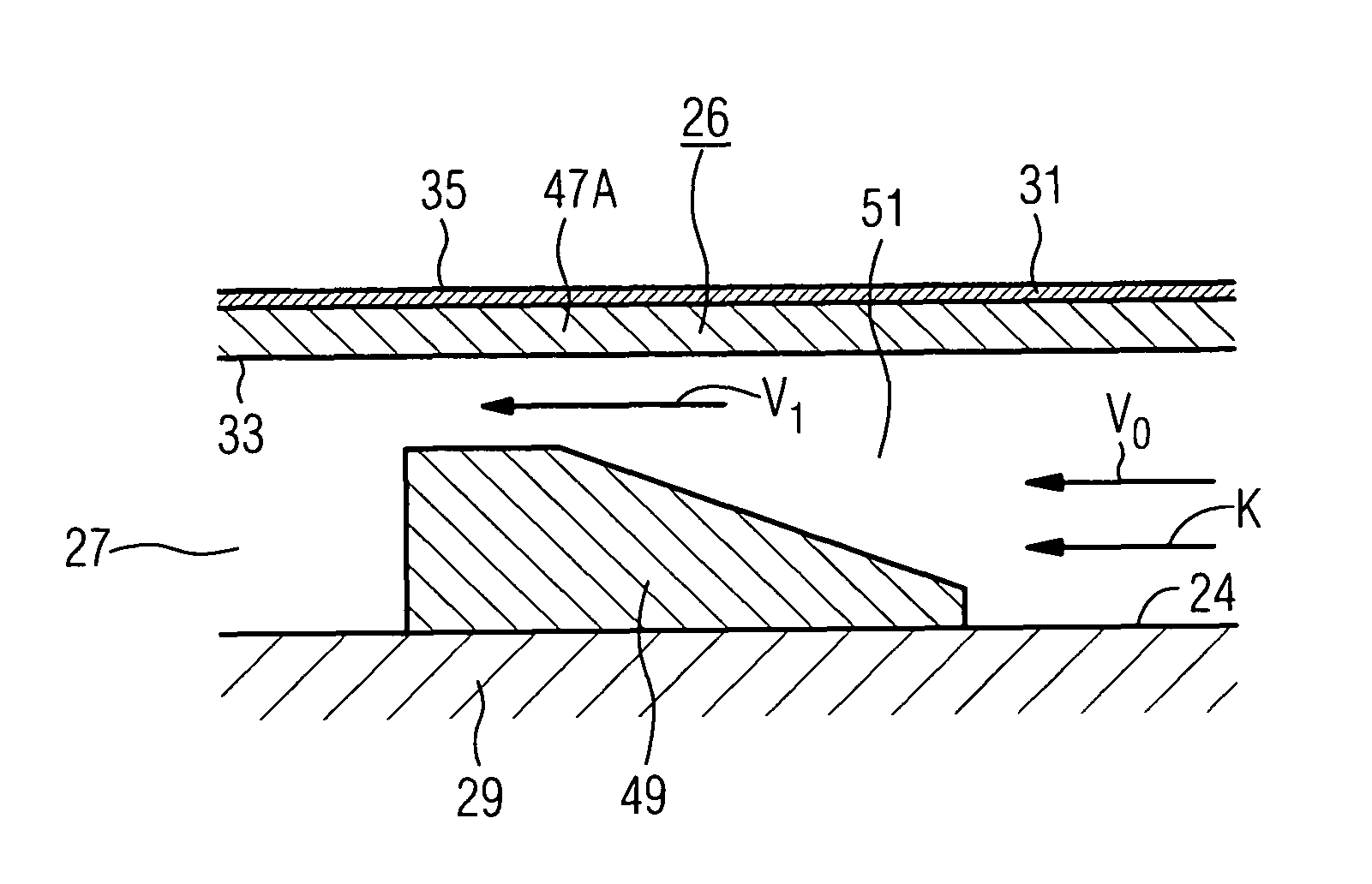
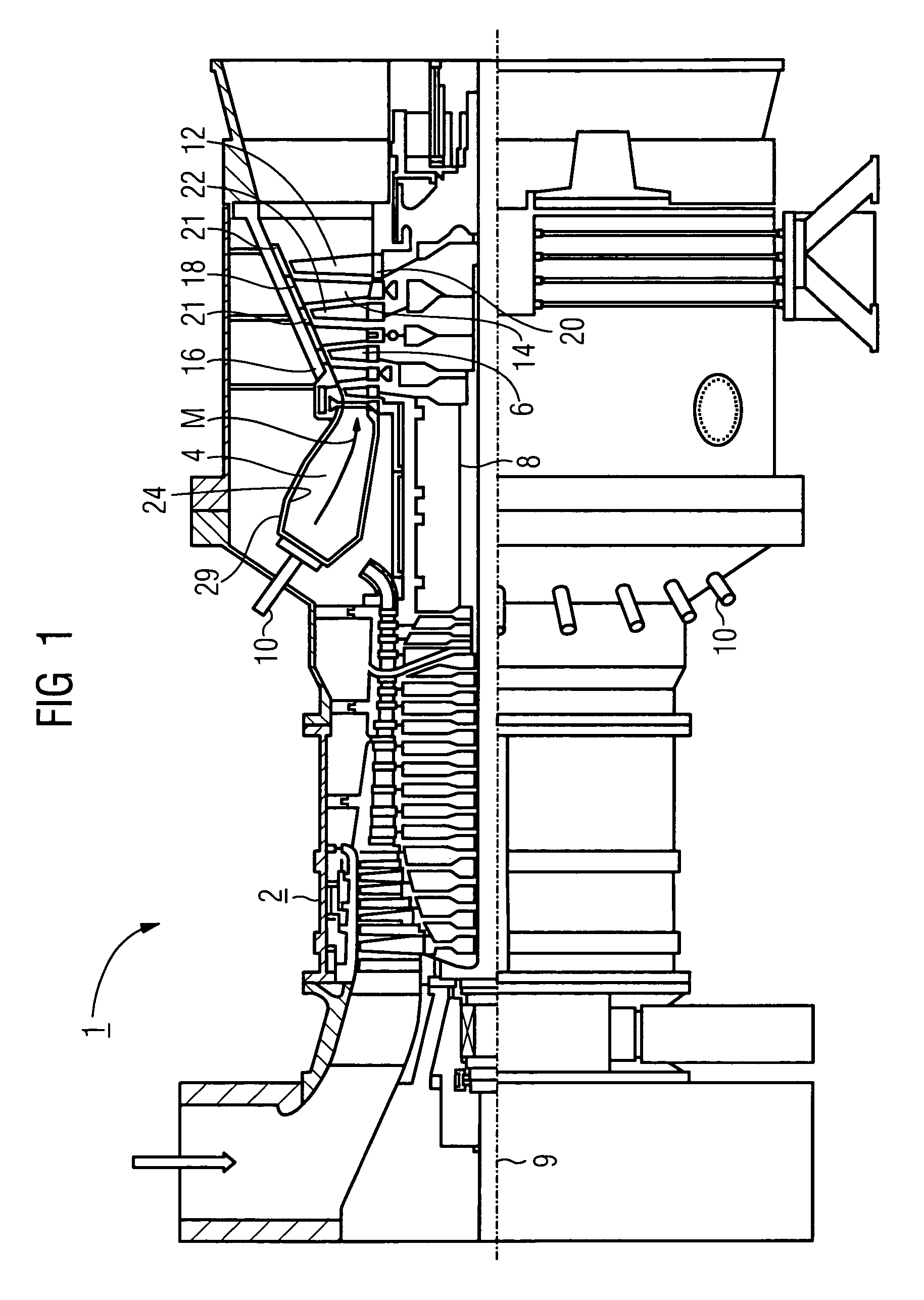
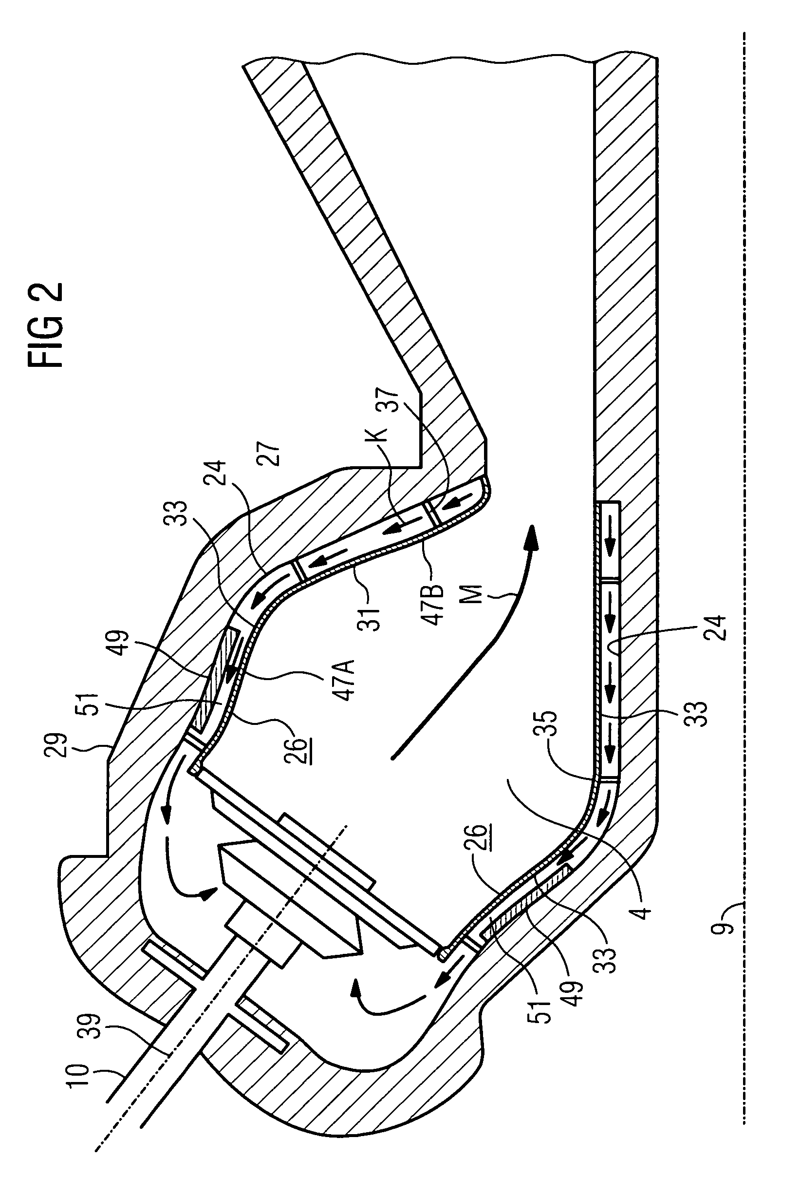
[0032]Identical parts are provided with the same reference characters in all the figures.

[0033]The gas turbine 1 according to FIG. 1 has a compressor 2 for combustion air, a combustion chamber 4 and a turbine 6 for driving the compressor 2 and a generator or machine (not shown). In addition, the turbine 6 and the compressor 2 are disposed on a common turbine shaft 8, also referred to as a turbine rotor, to which the generator or, as the case may be, the machine is also connected and which is rotatably mounted about its central axis 9. The combustion chamber 4 implemented in the manner of an annular combustion chamber is equipped with a plurality of burners 10 for combusting a liquid or gaseous fuel.

[0034]The turbine 6 has a number of rotatable blades 12 connected to the turbine shaft 8. The blades 12 are disposed in an annular cascade shape on the turbine shaft 8 and thus form a number of blade rows. The turbine 6 further comprises a number of stationary guide vanes 14 which are als...


PUM


Abstract

The invention relates to a combustion chamber of a gas turbine, inside of which a supplied fuel is reacted with supplied combustion air in order to produce a working medium. The inside of the combustion chamber wall is provided with a lining formed from a number of heat shield elements. The or each heat shield element, together with the combustion chamber wall, forms an interior space that can be subjected to the action of a coolant. The aim of the invention is to provide a combustion chamber with a comparatively simple design that has a high system efficiency. To this end, the invention provides that a flow element is placed in the respective interior space while serving to effect a locally specific control of the flow of coolant.

Description

CROSS REFERENCE TO RELATED APPLICATION[0001]This application is the US National Stage of International Application No. PCT / EP2004 / 004442, filed Apr. 27, 2004 and claims the benefit thereof. The International Application claims the benefits of German Patent application No. 03012441.6 DE filed May 30, 2003, both of the applications are incorporated by reference herein in their entirety.FIELD OF THE INVENTION[0002]The invention relates to a combustion chamber for a gas turbine, the combustion chamber wall of which is provided on the inside with a lining formed from a plurality of heat shield elements, wherein the heat shield element or each heat shield element forms an inner space which can be subjected to the action of a cooling medium. The invention further relates to a gas turbine having a combustion chamber of said kind.BACKGROUND OF THE INVENTION[0003]Combustion chambers form part of gas turbines, which are used in many fields for driving generators or machines. In such applicatio...

Claims


Application Information

Patent Timeline
IPC IPC(8): F02C1/00F23R3/00
CPCF23R3/005
Inventor HUTH, MICHAELTIEMANN, PETEROLTMANNS, LEGAL REPRESENTATIVE, IRIS
Owner SIEMENS AG
Why Eureka
Try Eureka