Display apparatus

a technology of display apparatus and display screen, which is applied in the field of display screen, can solve the problems of pupil misalignment, image cannot be drawn on the retina of the user, image cannot be drawn on the retina, etc., and achieve the effects of reducing the problem of pupil misalignment, reducing beam utilization efficiency, and increasing power consumption

Active Publication Date: 2012-08-21
PANASONIC CORP
View PDF19 Cites 198 Cited by
  • Summary
  • Abstract
  • Description
  • Claims
  • Application Information

AI Technical Summary

Benefits of technology

[0080]The display apparatus of the present invention allows an HMD to be capable of reducing the problem of the pupil misalignment, because the deflection unit is given deflection characteristics of suppressing image distortion caused by a change in relative positions of the deflection unit and a user's pupil with respective to each other.
[0081]Further, since the deflection unit of the display apparatus of the present invention deflects a beam such that the beam enters the user's pupil at different positions depending on the incidence angle at which the beam enters the pupil, a beam-scan display apparatus such as an HMD can reduce the problem of the pupil misalignment without having plural deflection focal points. Since there is no need to provide plural deflection focal points, it is also possible to prevent problems involved with plural deflection focal points, such as: doubly drawing images on the user's retinas; lower efficiency for beam utilization; the need of a high-power light source; higher power consumption; complication of the method for manufacturing the deflection unit; deterioration of the characteristics of the deflection unit; and complication of the display apparatus as a whole.
[0082]Furthermore, the image display apparatus of the present invention can display high-resolution images that are high in luminance and color reproducibility, and allow the user to view images with at least one of the user's eyes even when an eyeball rotation causes a pupil movement. Therefore, it is possible to provide an image display apparatus with which missing of image output and so on does not occur, while being small in size and low in power consumption.
[0083]In addition, with the display apparatus of the present invention, in the case where the deflection unit deflects display light toward plural focal positions so as to adapt to a change in the pupil position caused by an eyeball rotation, it is possible to reduce changes in the position or size of a displayed image, which occur when a focal position corresponding to the pupil position is switched to another focal position. Further, since such changes in the position or size become more significant as the deflection unit is closer to the user's eye, this structure allows the deflection unit to be placed near the user's eye. Furthermore, as a result of solving the problem with providing the deflection unit with plural focal points as a countermeasure against the pupil misalignment, it is possible to provide an HMD having a larger screen with a wider angle of view, which is likely to cause the pupil misalignment.
[0084]Moreover, the display apparatus of the present invention solves the problem of the pupil misalignment caused by wearing the apparatus even when the sliding down of eyeglasses occurs with an eyeglass-type HMD. As a result, the situation where images cannot be viewed is less likely to occur. Further, reducing problems with the sliding down of eyeglasses makes it possible to provide a heavy HMD, an HMD whose weight balance is at its front (the lens portion), and an HMD having small contact areas near the user's nose or ears, all of which are relatively likely to cause the sliding down of eyeglasses. In addition, since problems with eyeglass-type HMDs can be reduced, HMDs can be eyeglass-type HMDs.

Problems solved by technology

When this causes misalignment between a deflection focal point and the pupil position, the beams deflected by the deflection mirrors do not pass through the pupils, resulting in a situation where images cannot be drawn on the user's retinas.
However, when the user's eyeball rotates to the left as shown in FIG. 24, the deflection focal point falls outside the pupil, thereby causing the pupil misalignment and thus images cannot be drawn on the retina.
In the case where the diameter of the user's pupil is 3 millimeters, for example, the pupil misalignment occurs when the pupil moves 1.5 millimeters or more, thereby hindering the user from viewing images.
Consequently, there is a problem that the size and weight of such an image display apparatus makes it difficult for the user to use the apparatus for a long time.
In addition, to pursue high-resolution output images, the image display apparatus becomes larger, resulting in a heavier burden on the user.
When an output image is to be viewed using such an eyeglass-type image display apparatus, a situation sometimes arises in which a ray of light projected onto the user's pupil is shielded by the iris and thus the visual field is narrowed, hindering the user from viewing the entire or a part of the output image or causing uneven luminance in the image.
Therefore, the larger the angle of view (viewing angle) of images displayed by an HMD is, the larger the rotation angle of eyeball rotation is like to be, and the more likely it is that the pupil misalignment occurs.
However, when an eyeball rotation causes the pupil to move to a pupil position B, the pupil misalignment occurs because the beams focused on the focal point A cannot pass through the pupil.
In this case, the user cannot view images.

Method used


Image

  • Display apparatus
  • Display apparatus
  • Display apparatus

Examples


embodiment 1

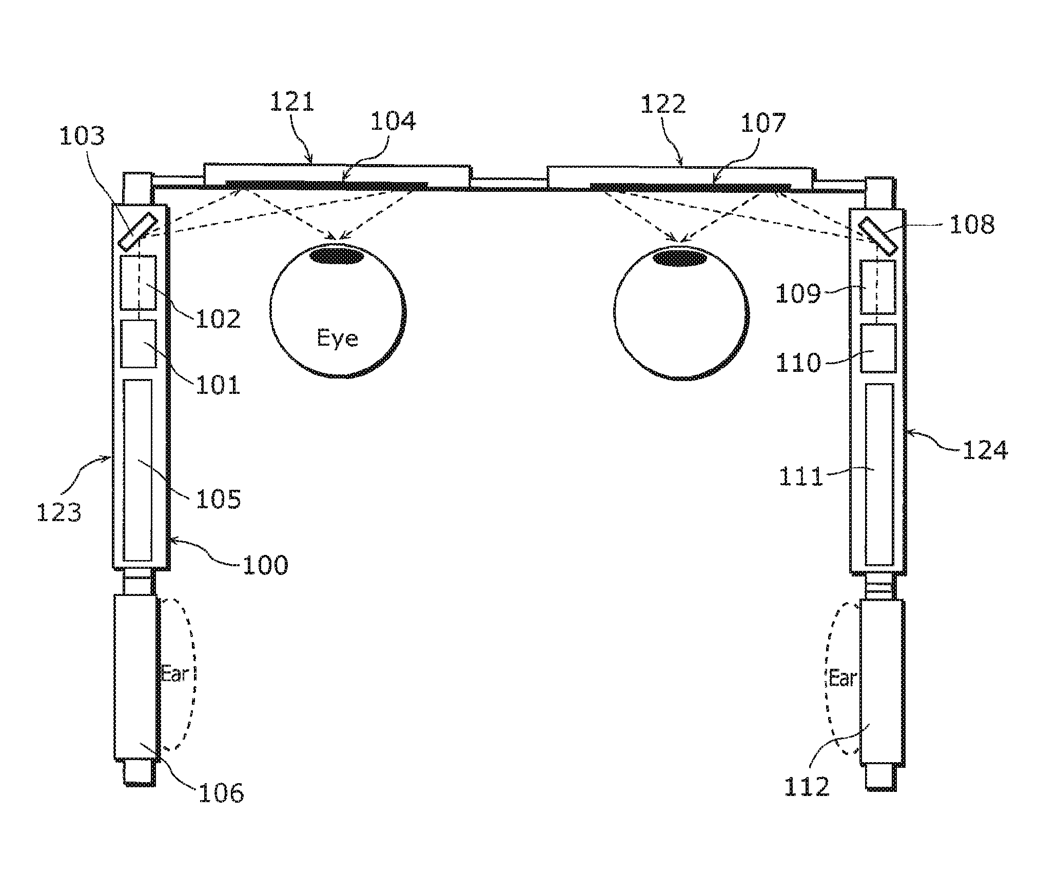
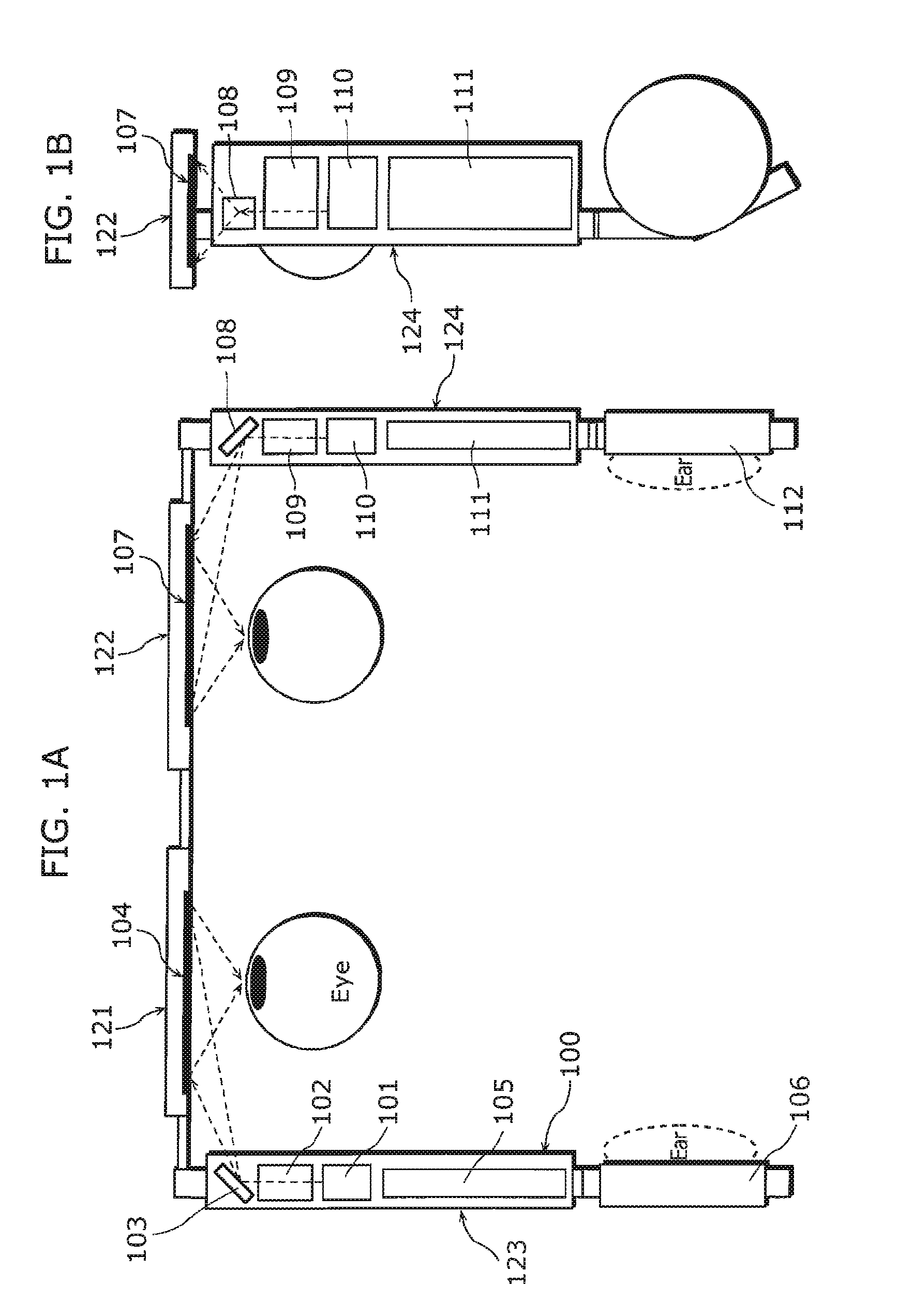
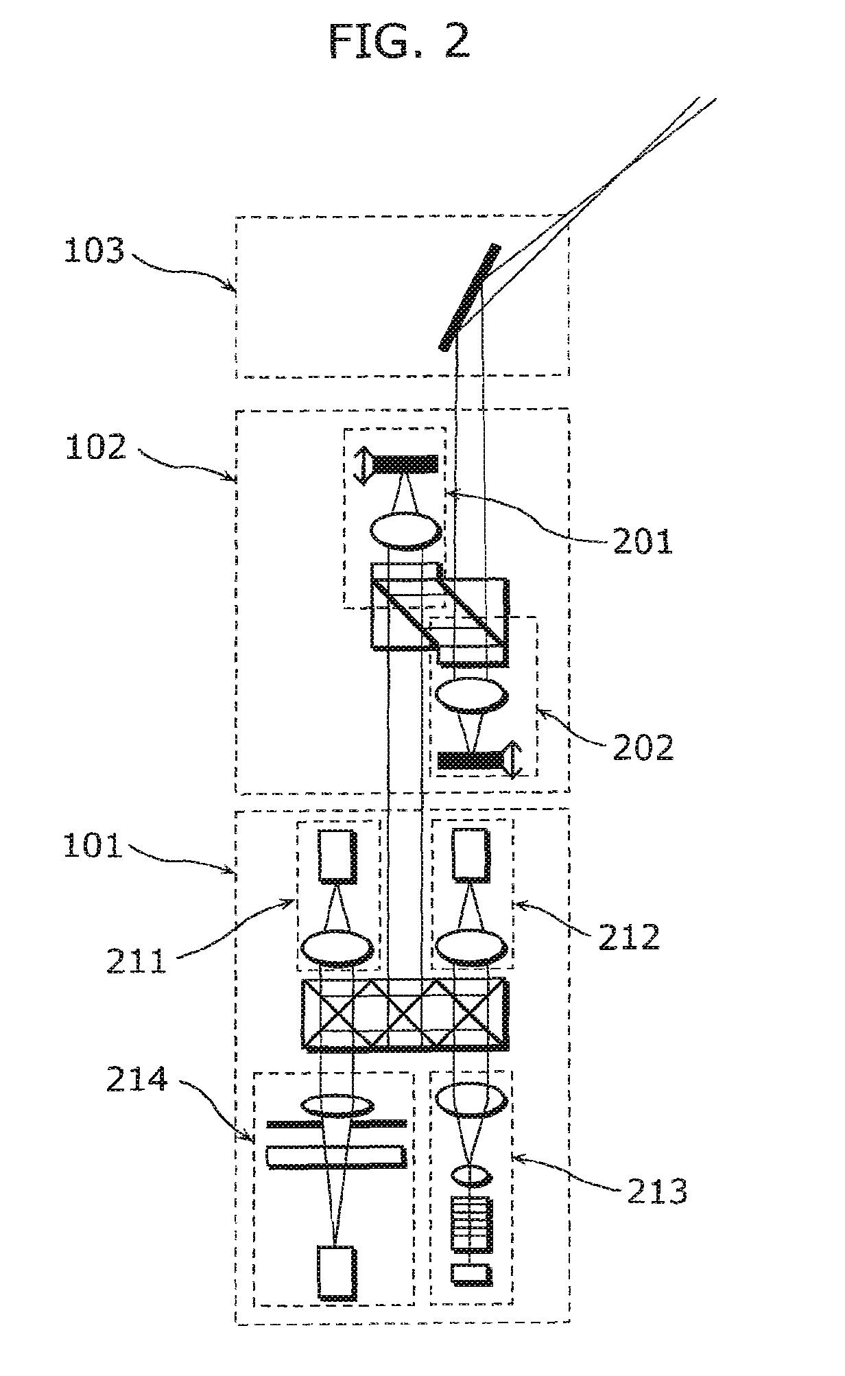
[0191]Described hereinafter with reference to FIGS. 1A, 1B, 2 and 3 is an eyeglass-type HMD as a beam-scan display apparatus (also referred to as “image display apparatus” or “display apparatus”) according to Embodiment 1 of the present invention. It is to be noted that FIG. 1A is a plan view of the display apparatus, FIG. 1B is a side view of the display apparatus, FIG. 2 is a detail view of a portion of FIG. 1A, and FIG. 3 is a functional block diagram of the display apparatus.

[0192]The eyeglass-type HMD according to Embodiment 1 includes: lenses 121 and 122 provided in front of the user's left and right eyes, respectively; and a pair of temples 123 and 124 each having one end connected to a corresponding one of the lenses 121 and 122 and the other end fixed to the user's temporal region.

[0193]As shown in FIGS. 1A, 1B, and 2, the display apparatus includes: light sources 101 and 110 which emit beams for drawing each of pixels constituting a display image; wavefront shape change un...

embodiment 2

[0244]With reference to FIG. 7, a display apparatus 10 according to Embodiment 2 of the present invention shall be described. FIG. 7 is a schematic structural diagram of the display apparatus 10.

[0245]The display apparatus 10 in Embodiment 2 includes: image output units 3R and 3L which output emitted beams 2; a deflection unit 15 which deflects the emitted beams 2 toward the user's eyes 8R and 8L (beam focusing positions 11R and 11L); control units 5R and 5L which control the image output units 3R and 3L; and an overall control unit 6 which performs overall control over the processing of the control units 5R and 5L. It is to be noted that the image output units 3R and 3L respectively include light sources 1R and 1L, scan units 4R and 4L which two-dimensionally scan the emitted beams 2 emitted from the light sources 1R and 1L, and a light detection unit 17. Further, the deflection unit 15 includes hologram mirrors 15R and 15L provided at positions facing the right and left eyes 8R an...

embodiment 3

[0277]With reference to FIG. 12, a display apparatus 30 according to Embodiment 3 of the present invention shall be described. FIG. 12 is a schematic structural diagram of the display apparatus 30. It is to be noted that the basic structure of the display apparatus 30 is common to that of the display apparatus 10 illustrated in FIG. 7. Thus, a detailed description of the common aspects shall be omitted, and the following description centers on different aspects.

[0278]With the display apparatus 30 according to Embodiment 3, the hologram mirrors 15L and 15R project, onto the user's eyes 8L and 8R, respectively, images with different visual fields 31. It is to be noted that elliptical areas surrounded by broken lines in FIG. 12 represent the visual fields 31, one being a left visual field 31L and another being a right visual field 31R. Here, the pupil-to-pupil distance 9 is equal to the focus-to-focus distance 12, which is a distance between the beam focusing positions 11L and 11R.

[027...


PUM


Abstract

A display apparatus that displays an image on a retina of a user, the display apparatus comprising: an image output unit (100) which includes a light source (101, 110), a wavefront shape change unit (102, 109), and a scan unit (103, 108) and is configured to output display light for displaying the image; and a deflection unit (104, 107) configured to deflect, toward an eye of the user, the display light outputted by the image output unit (100). The deflection unit (104, 107) has a deflection characteristic of suppressing image distortion caused by a change in relative position of the deflection unit (104, 107) with respect to a pupil of the user.

Description

TECHNICAL FIELD[0001]The present invention relates to a display apparatus such as a head-mounted display (HMD).BACKGROUND ART[0002]One of conventional methods used for display apparatuses such as head-mounted displays (HMDs) is a method of directly drawing images on the retinas of the user's eyes by two-dimensionally scanning laser beams (hereinafter described as a laser scanning method) (for example, see Patent Reference 1). The display apparatus according to the laser scanning method is also known as a retinal scanning display, retinal irradiation display, retinal direct-drawing display, laser scanning display (RSD), direct-view-type display, virtual retinal display (VRD), and so on.[0003]HMDs according to the laser scanning method generally include a scan unit which two-dimensionally scans laser beams emitted from a laser light source, and a deflection mirror, such as a lens or a mirror provided in front of the user's eyes, which deflects the beams toward the user's pupils so tha...

Claims


Application Information

Patent Timeline
Patent Type & Authority Patents(United States)
IPC IPC(8): G03B21/26G02B27/14G09G5/00
CPCG02B26/101G02B27/0172G02B26/10G02B2027/011G02B2027/014G02B2027/0187
Inventor YAMAMOTO, KAKUYAKASAZUMI, KENICHIITOH, TATSUOKUROZUKA, AKIRASUGIYAMA, KEIJI
Owner PANASONIC CORP
Why Eureka
Try Eureka