Thrust box and skid for a horizontally mounted submersible pump

a horizontal mounted, submerged pump technology, applied in the direction of sliding contact bearings, machines/engines, liquid fuel engines, etc., can solve the problems of insufficient circulated and cooled lubricant in the thrust box, the inability to pump extremely large volumes of fluid, and the inability to quickly destroy the bearings of the engine or motor, etc., to achieve the effect of reducing the number of bearings needed

Active Publication Date: 2012-08-21
EXTRACT SURFACE SYST LLC
View PDF17 Cites 14 Cited by
  • Summary
  • Abstract
  • Description
  • Claims
  • Application Information

AI Technical Summary

Benefits of technology

[0009]The improved thrust box also utilizes equalizing thrust bearings to transfer the force of the thrust from the shaft to the case of the thrust box and then back into the pump. The use of thrust bearings greatly reduces the number of bearings necessary over using angle needled bearings. The thrust bearings also allow the thrust box to operate both clockwise and counterclockwise without having to change out bearings as would be necessary with using angled needle bearings.
[0010]The thrust bearing can be equipped with a heat sensor. This allows the monitoring of the internal temperature of the thrust bearing and not just the temperature of the lubricant thus providing indication as to maintenance problems before there is a catastrophic failure. Likewise the thrust bearing can be equipped with a load sensor. Changes of the load on the thrust bearing can provide the operator an indication of the condition of the pump.

Problems solved by technology

These submersible pumps have the capability of pumping extremely large volumes of fluid in a very short time.
If the combustion engine or electric motor were coupled directly to the submersible pump this force would quickly destroy the bearings of the engine or motor.
First, the thrust boxes on the market do not have a circulated and cooled lubricant.
This creates problems with heat build up and lubricant failure which greatly shortens the life of the thrust box.
Second, the thrust boxes rely upon seals which are held in place by clip rings mounted in grooves in the shaft.
The groove cut in the shaft can introduce stress cracks in the shaft.
Because of the cost of maintaining inventory, most manufacturers custom make these shafts per the operator's specification.
This creates increased down time and loss of operating revenue for the operator if they must change out the shaft and / or thrust box due to relocating the equipment or mechanical failure of the equipment.
This too leads to increased down time and loss of operating revenue for the operator.

Method used


Image

  • Thrust box and skid for a horizontally mounted submersible pump
  • Thrust box and skid for a horizontally mounted submersible pump
  • Thrust box and skid for a horizontally mounted submersible pump

Examples


Embodiment Construction

)

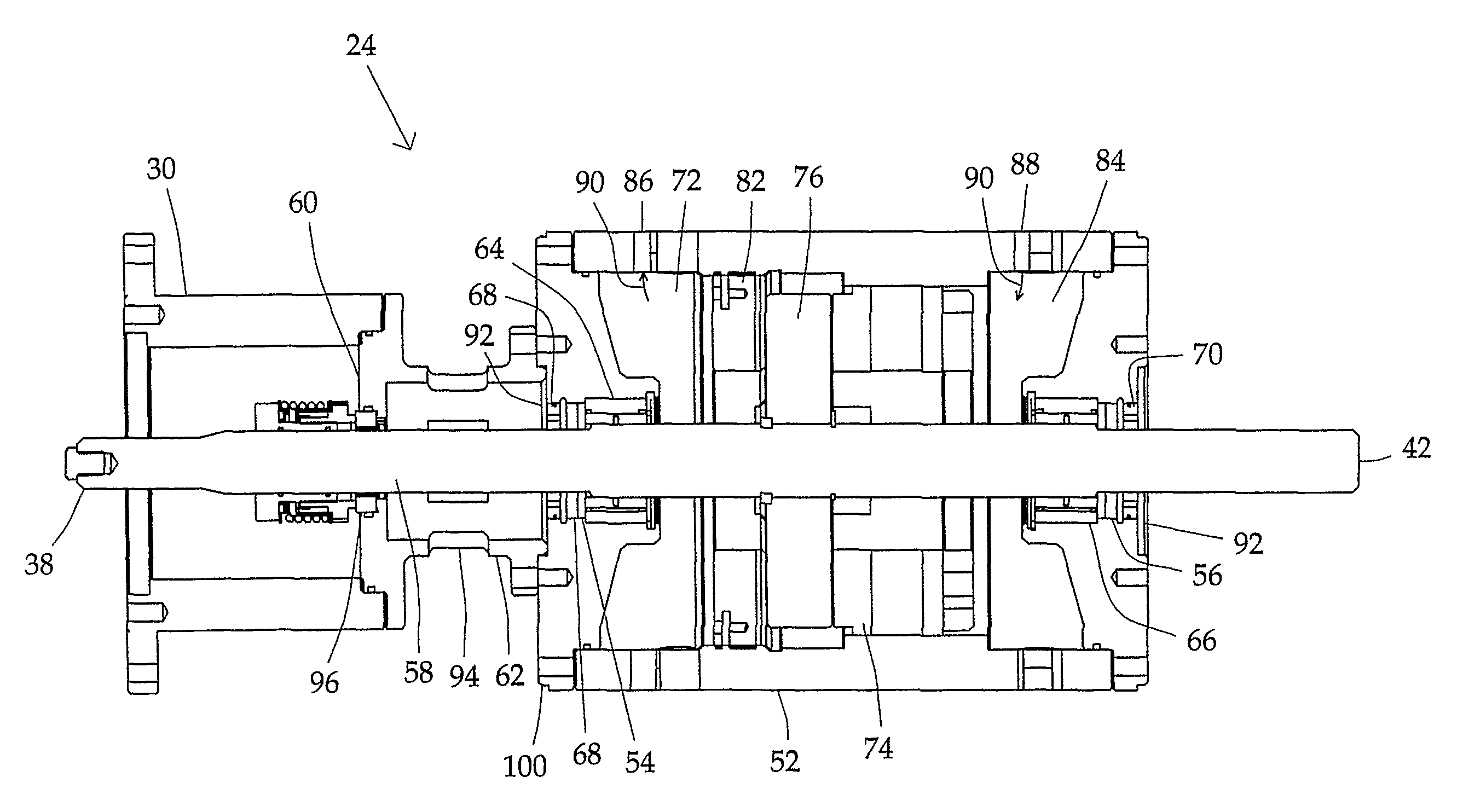
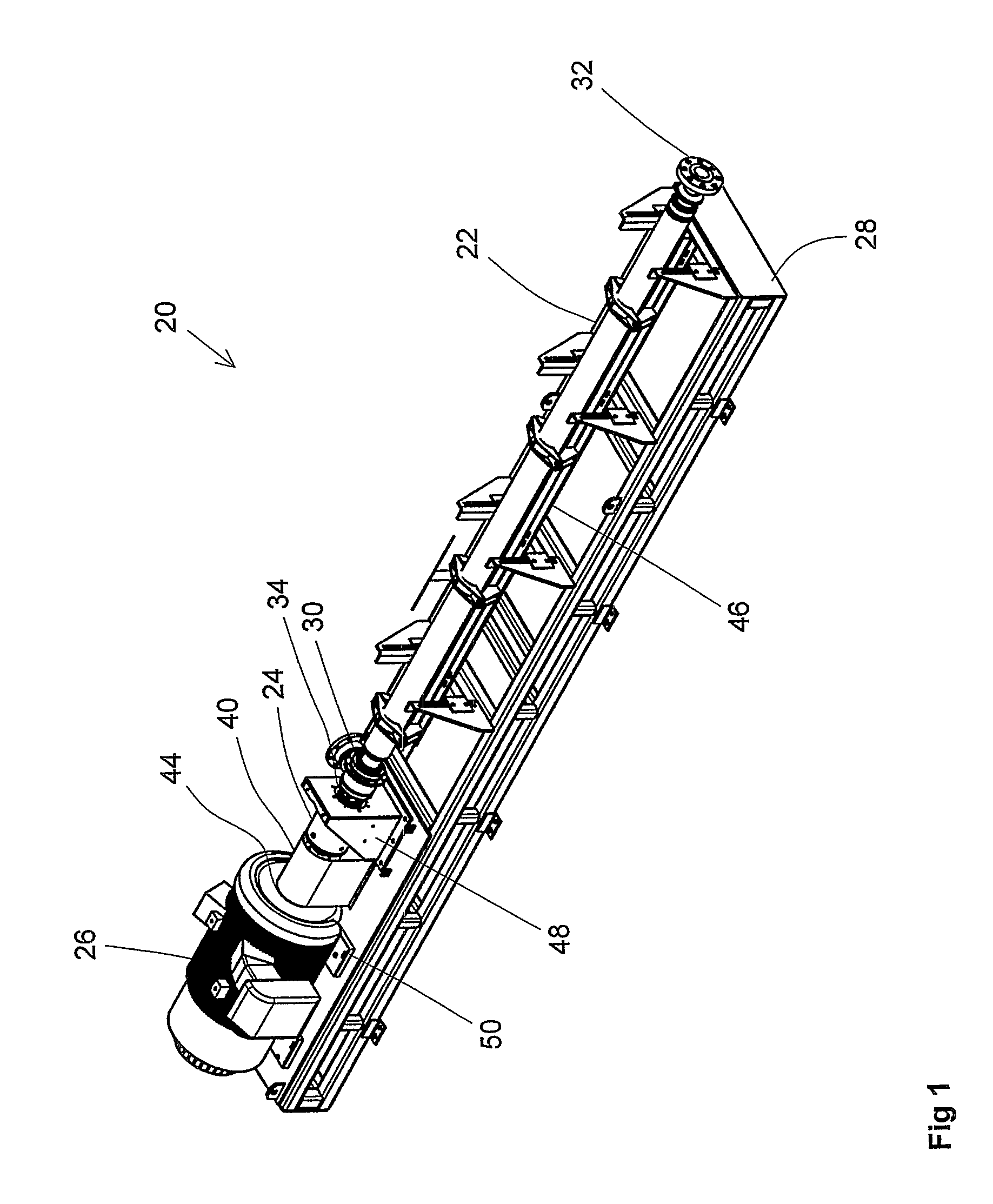
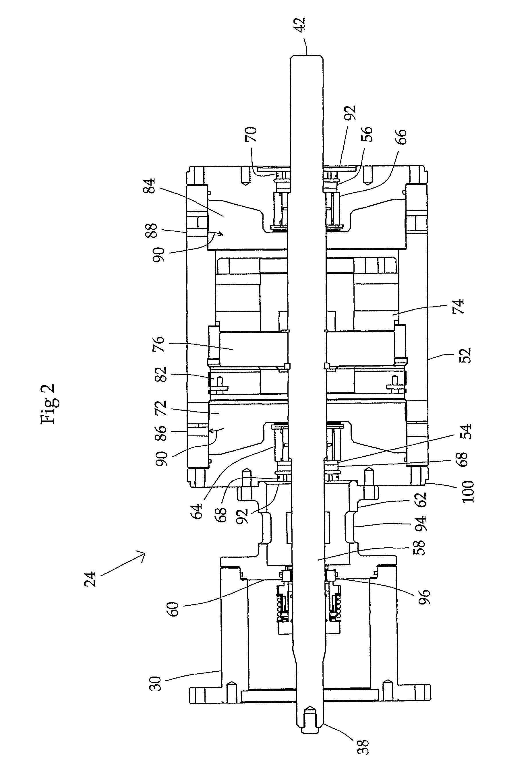
[0020]Turning now to the drawings wherein like reference characters indicate like or similar parts throughout, FIG. 1 shows a skid mounted submersible pump which has four main components, the submersible pump 22, the thrust chamber 24, the motor 26 and the skid 28. The pump 22 has an inlet 30 and an outlet 32. A first coupler 34 connects the pump shaft 36 to the first end of the thrust chamber shaft. A second coupler 40 connects the second end 42 of the thrust chamber shaft to the shaft 44 of the motor 26.

[0021]FIG. 1 shows the skid mounted horizontal submersible pump with an electric motor 26. Other drive mechanisms including but not limited to an internal combustion engine or hydraulic motor could also be used to power the horizontal submersible pump 22.

[0022]The skid 28 has a cradle 46 which supports the pump 22. A thrust chamber mounting bracket 48 holds the thrust chamber 24 in place. The skid 28 also has the motor mounting brackets 50 which hold the motor 26 in place.

[0023]Wh...


PUM


Abstract

A thrust chamber using a single thrust bearing and having seals secured to the thrust chamber case. Also a skid for a horizontally mounted submersible pump, thrust chamber and drive mechanism. The skid having a thrust chamber mounting bracket which provides positive mounting locations thus allowing for the change out of the thrust chamber without removing the drive mechanism.

Description

FIELD OF THE INVENTION[0001]The present invention relates generally to horizontally mounted submersible pumps. More specifically, the present invention relates to thrust box and their use in conjunction with a horizontally mounted submersible pump.BACKGROUND OF THE INVENTION[0002]Submersible pumps like the kind used in oil fields are designed for downhole applications. They typically have a cylindrical shape with a diameter that allows them to be inserted within the casing of the well. The length of the pump can vary from 20 feet to 80 feet or more depending upon the amount of pressure and volume necessary for the application. These submersible pumps have the capability of pumping extremely large volumes of fluid in a very short time. Because of their ability to pump large volumes of fluid very rapidly, there are many surface applications for these submersible pumps. In order to use the pumps on the surface it is necessary to mount the pump horizontally on a skid. The pump can then ...

Claims


Application Information

Patent Timeline
Patent Type & Authority Patents(United States)
IPC IPC(8): F16C19/30
CPCF04D13/086F04D29/0462F04D29/606F04D29/628
Inventor GARDNER, JAMES
Owner EXTRACT SURFACE SYST LLC
Why Eureka
Try Eureka