Six axis motion control apparatus

a technology of motion control and apparatus, applied in the direction of instruments, optical elements, optics, etc., can solve the problems of time-consuming, laborious, time-consuming, etc., and achieve the effect of eliminating human variability of operators, facilitating movement of objects, and more accurate and comprehensive results

Active Publication Date: 2012-08-21
CAPTURE 3D
View PDF10 Cites 6 Cited by
  • Summary
  • Abstract
  • Description
  • Claims
  • Application Information

AI Technical Summary

Benefits of technology

[0013]A motion control apparatus for non-contact three dimensional scanning of a surface of an object is provided. The motion control apparatus uses a computer and associated software to automate the measurement of the object to be scanned. The ability to automate scanning of the object produces more accurate, faster, and comprehensive results. The motion control apparatus is used to automate the measurement process for small to mid-size parts. The motion control apparatus is configured to record a measurement plan used to measure the object being scanned. Using the measurement plan, the motion control apparatus is able to repeat the process over and over much quicker than is manually possible by an operator. The motion control apparatus may measure each object in precisely the same way by using the repetitive process of the machine, eliminating the human variability of the operators. The motion control apparatus uses precision engineered servo motors and stages to facilitate movement of the object to be scanned and a scanner for obtaining a plurality of views and perspectives of the object that is measured.
[0018]The ability of the object support assembly to move parallel to the second axis is enabled by a plate that is coupled to the pair of spaced apart tracks. The plate may include four brackets, wherein two brackets are coupled to each of the spaced apart tracks. The brackets of the plate enable the plate to move linearly and parallel to the first axis. The plate is also supported by the pair of spaced apart tracks that are supported by the base. On top of the plate there is a track that is parallel to the second axis. The object support assembly is coupled to the track on the top surface of the plate. The track on the top surface of the plate facilitates linear movement parallel to the second axis. The linear movement parallel to the first axis is independent of the linear movement parallel to the second axis and vice versa. The object support assembly which is coupled to the track on top of the plate is configured to linearly move parallel to the first axis and the second axis.

Problems solved by technology

The ability to provide the designed geometry to meet the designer's intent and achieve the engineering dimensional requirement to deliver the intended fit and functionality is an ongoing challenge during the manufacturing process.
The task of measuring these features can be time-consuming with a tactile measuring device.
Even after the measuring is complete and the report is generated it is still difficult to identify the problematic areas and determine corrective action due to the lack of full part information.
However, scanning and measuring an object by having an operator holding the scanner is tedious, time consuming, and not conducive to repetition.
The problem with using a tripod is the limits of various perspectives that are achieved when scanning an object.
Unfortunately, the scan of the object or work piece with these devices may produce undesired shadows, making completely automated scanning less feasible.
However, even with the technological advances associated with CMM devices, collecting measurement data and manual inspection techniques are very time consuming.
Unfortunately, these scanners may be limited with respect to some of its movements.
This may result in less comprehensive scans and measurements of the object with respect to certain perspectives.

Method used


Image

  • Six axis motion control apparatus
  • Six axis motion control apparatus
  • Six axis motion control apparatus

Examples


first embodiment

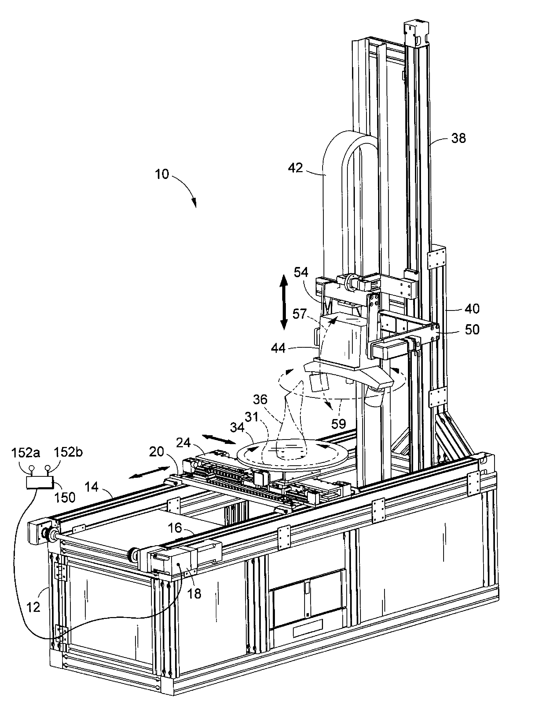
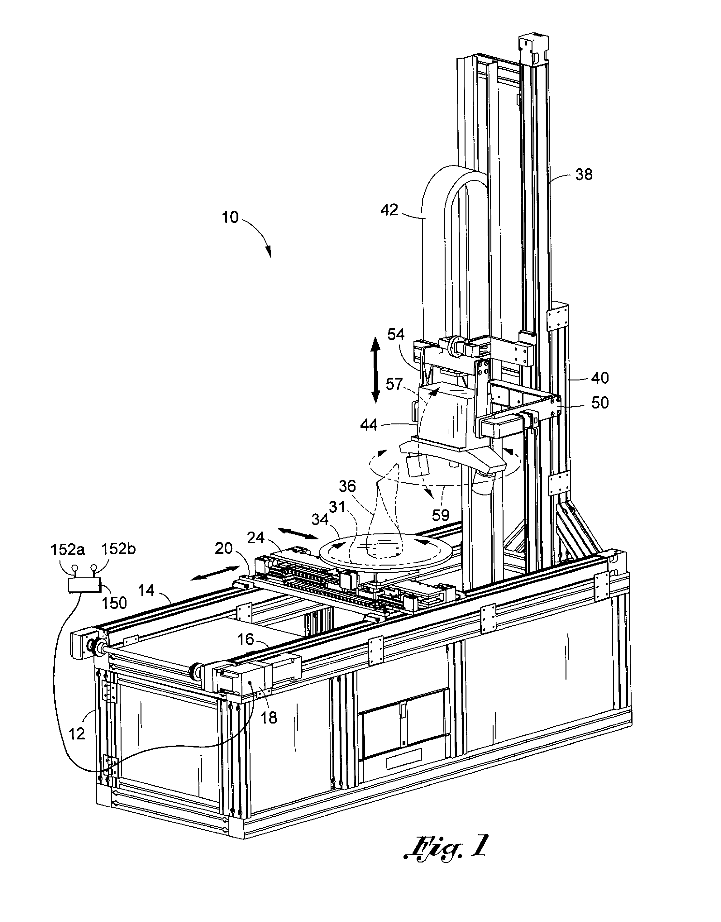
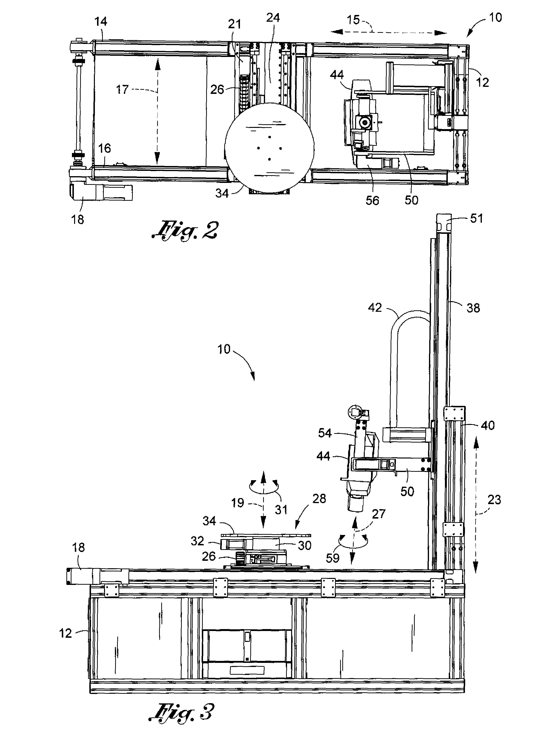
[0040]Referring now to FIG. 1, a six axis motion control apparatus 10 constructed in accordance with the apparatus is provided. The motion control apparatus 10 is used to move an object 36 or work piece to be scanned with respect to a white light volumetric scanner 44. Additionally, the scanner 44 may be moved to capture the object 36 from various perspectives to enable a more comprehensive scan of the object 36. The apparatus 10 is configured for linear motion, rotational motion, and pivoting about a plurality of axes. The apparatus 10 includes a base 12. The base 12 may be formed in the shape of a rectangular box. However, the base 12 is not limited to a rectangular shape and may encompass a variety of different shapes and sizes. A plurality of castors (not shown) may also be coupled to the underside of the base 12 so that the apparatus 10 is portable. The base 12 is used to support the various parts that facilitate movement of the object 36 and the white light volumetric scanner ...

second embodiment

[0052]Referring now to FIG. 7, the six axis motion control apparatus 100 is provided. The motion control apparatus 100 includes a frame 102. The frame 102 may be constructed from various materials including metal or wood by way of example. The frame 102 may be formed in the shape of a rectangular box. It is contemplated that the frame 102 may be constructed in a variety of shapes and sizes. Attached to the bottom of the frame 102 is a plurality of castors 112, providing portability to the frame 102 of the apparatus 100.

[0053]Referring now to FIG. 9, a first track 104 and a second track 106 are provided. The first track 104 is coupled to opposing bars comprising one side of the frame 102. The first track 104 defines a first axis 128 extending latitudinally. The first track 104 may include a slot or plurality of slots for receiving an extension part from the underside of the second track 106. The extension on the underside of the second track 106 is configured to attach to the slot or...


PUM


Abstract

A motion control apparatus for measuring and scanning an object. The motion control apparatus includes a base. The motion control apparatus also includes an object support assembly that is coupled to the base. The object support assembly receives the object to be scanned and measured. The motion control apparatus includes a scanner track that extends above from the base. The scanner and object are moveable about multiple axes to position to the scanner with respect to the object for viewing the object by the scanner for obtaining measurements of the object.

Description

CROSS-REFERENCE TO RELATED APPLICATIONS[0001]Not ApplicableSTATEMENT RE: FEDERALLY SPONSORED RESEARCH / DEVELOPMENT[0002]Not ApplicableBACKGROUND[0003]1. Field of the Invention[0004]The present invention relates to a motion control apparatus and more particularly to a six axis motion control apparatus for non-contact scanning of a surface of an object.[0005]2. Description of the Prior Art[0006]Three dimensional scanning is an important component associated with the manufacturing process. Optical three dimensional scanning is accurate and a cost-effective alternative delivering more dimensional information to aid in quality control and process optimization. The ability to provide the designed geometry to meet the designer's intent and achieve the engineering dimensional requirement to deliver the intended fit and functionality is an ongoing challenge during the manufacturing process. Optical three dimensional scanning is based on the principle of triangulation. A sensor unit projects d...

Claims


Application Information

Patent Timeline
Patent Type & Authority Patents(United States)
IPC IPC(8): G01C19/00
CPCG01B11/24G01N21/9515G01N2021/9518
Inventor WHITE, RICHARD P.WADE, DAVIDWEDE, HENRY
Owner CAPTURE 3D
Why Eureka
Try Eureka