Projector having a projection angle adjusting mechanism

a projection angle and adjustment mechanism technology, applied in the field of projectors, can solve the problems of limited image projection positions, limited display space for realizing augmented reality, and limited projection spa

Inactive Publication Date: 2012-08-28
PANASONIC CORP
View PDF28 Cites 23 Cited by
  • Summary
  • Abstract
  • Description
  • Claims
  • Application Information

AI Technical Summary

Benefits of technology

[0008]The present invention was developed to solve the above problems and an object thereof is to provide a projector capable of freely operating and augmenting a projection space thereof and extending its application not only to image display, but also to illumination and decoration with colored light.

Problems solved by technology

However, image projection positions are limited in a conventional projector and a main body needs to be moved and adjusted in the case of changing a projection position, thereby presenting a problem of limiting a display space for realizing an augmented reality.
However, there is a problem of a limited projection space due to the above problems of moving the main body and making adjustments, which problems accompany a change of the image projection position.
Conventional projectors have a problem of a limited projection space (display space) as means for realizing an augmented reality, means for presenting information and images and means for illumination and decoration.

Method used


Image

  • Projector having a projection angle adjusting mechanism
  • Projector having a projection angle adjusting mechanism
  • Projector having a projection angle adjusting mechanism

Examples


first embodiment

[0026](First Embodiment)

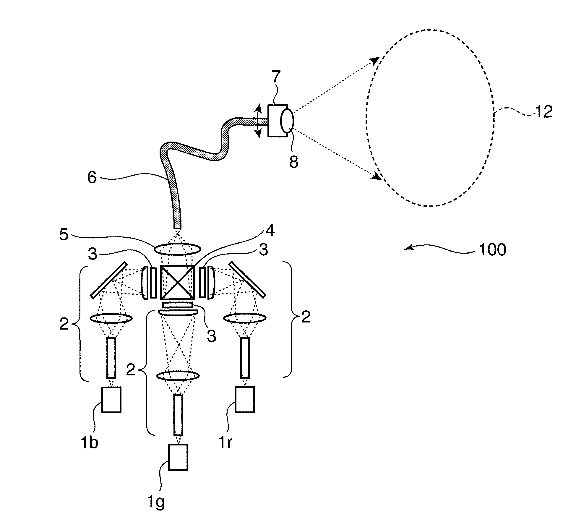
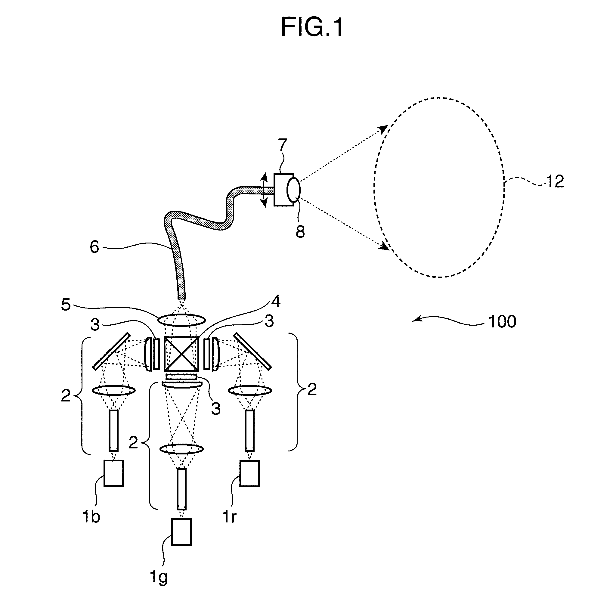
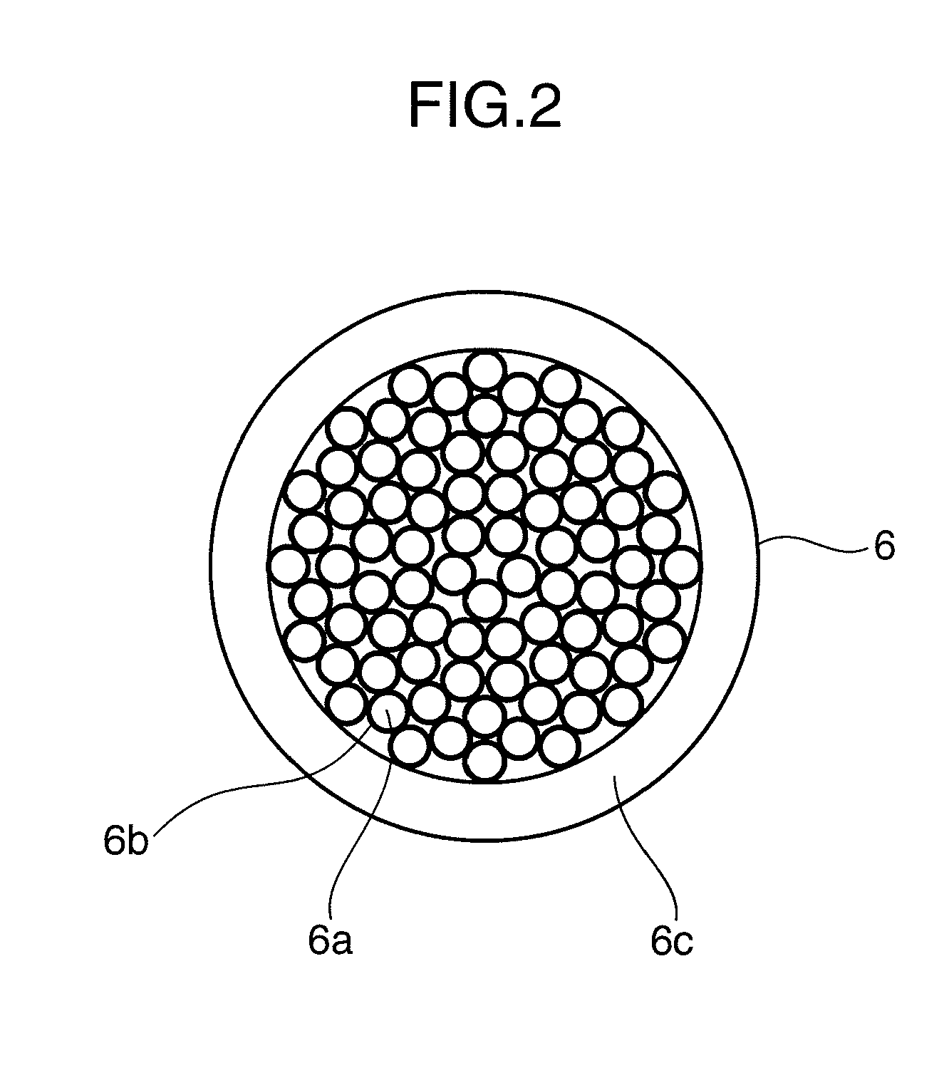
[0027]FIG. 1 is a schematic construction diagram of a multipurpose projector 100 according to a first embodiment of the present invention, and FIG. 2 is a schematic section of an input / output plane of a fiber bundle 6 according to the first embodiment of the present invention.

[0028]The multipurpose projector 100 shown in FIG. 1 is provided with laser beam sources 1r, 1g and 1b, an illumination optical system 2, a spatial modulation element 3, a multiplexing prism 4, a reduction projection optical system 5, a fiber bundle 6, a projection angle adjusting mechanism 7 and a projection lens 8. In this embodiment, the laser beam sources 1r, 1g and 1b correspond to an example of a laser beam source and the illumination optical system 2, the spatial modulation element 3, the multiplexing prism 4 and the reduction projection optical system 5 correspond to an example of an optical guide unit.

[0029]The laser beam source 1r emits a red laser beam having a directivity, th...

second embodiment

[0058](Second Embodiment)

[0059]FIG. 3 is a schematic construction diagram of a multipurpose projector 200 according to a second embodiment of the present invention. In FIG. 3, the same construction as the first embodiment is identified by the same reference numerals and not described.

[0060]The multipurpose projector 200 shown in FIG. 3 is provided with laser beam sources 1r, 1g and 1b, an illumination optical system 2, a spatial modulation element 3, a multiplexing prism 4, a reduction projection optical system 5, a fiber bundle 6, a projection angle adjusting mechanism 7, a projection lens 8, a switching element 9, a speckle noise removing mechanism 10 and a main projection lens 11.

[0061]The multipurpose projector 200 has the same construction as the multipurpose projector 100 up to the reduction projection optical system 5. The main projection lens 11 enlarges and projects modulated laser beams to a display space 13 different from the display space 12, to which laser beams are pro...

third embodiment

[0075](Third Embodiment)

[0076]FIG. 4 is a schematic construction diagram of a multipurpose projector 300 according to a third embodiment of the present invention. In FIG. 4, the same construction as the first and second embodiments is identified by the same reference numerals and not described.

[0077]The multipurpose projector 300 shown in FIG. 4 is provided with a laser beam source 1a, an illumination optical system 2, a reduction projection optical system 5, a projection lens 8, a speckle noise removing mechanism 10, a main projection lens 11, a spatial modulation element 31, a fiber bundle 61, a coupling lens 81 and a reflective polarizing element 91. In the third embodiment, the illumination optical system 2, the reduction projection optical system 5 and the spatial modulation element 31 correspond to an example of the optical guide unit.

[0078]The laser beam source 1a is a unit of three laser beam sources of three red, green and blue colors and emits laser beams of different colo...


PUM


Abstract

A multipurpose projector is provided with a fiber bundle including a plurality of cores fixedly arranged on an input plane and an output plane, laser beam sources for emitting laser beams having directivities, an optical guide unit for modulating the laser beams emitted from the laser beam sources and guiding the modulated laser beams to the input plane of the fiber bundle, a projection lens for enlarging and projecting the laser beams emerging from the output plane of the fiber bundle to a display space, and a projection angle adjusting mechanism disposed on the side of the output plane of the fiber bundle for adjusting projection angles of the laser beams projected from the projection lens. Thus, the projector can have its projection space freely operated and enlarged to extend its application not only to image display, but also to illumination and decoration with colored light.

Description

TECHNOLOGICAL FIELD[0001]The present invention relates to a projector for projecting an image and information.BACKGROUND ART[0002]Augmented reality as technology for augmenting sensory perception for reality with additional information by projecting or relating a virtual space to reality is being studied. Augmented reality is expected to be applied as a task support and entertainment in a reality environment. The projection of images (information) to a reality environment by a projector is used as one means for adding information to the reality environment in an augmented reality.[0003]However, image projection positions are limited in a conventional projector and a main body needs to be moved and adjusted in the case of changing a projection position, thereby presenting a problem of limiting a display space for realizing an augmented reality.[0004]As a method proposed thus far for moving an image projection position of a projector, a projection lens is shifted and pixels of a spati...

Claims


Application Information

Patent Timeline
Patent Type & Authority Patents(United States)
IPC IPC(8): G03B21/28
CPCG02B6/06G03B21/00G09F19/12H04N9/3105H04N9/3147H04N9/315H04N9/3161F21W2131/406G02B26/105G02B27/48G03B21/005
Inventor MIZUSHIMA, TETSUROYAMAMOTO, KAZUHISAKUROZUKA, AKIRAYAMAMOTO, KAKUYASUGIYAMA, KEIJI
Owner PANASONIC CORP
Why Eureka
Try Eureka