Cryostat having a magnet coil system, which comprises an LTS section and an encapsulated HTS section

a technology of magnet coils and cryostats, which is applied in the direction of superconducting magnets/coils, magnetic bodies, instruments, etc., can solve the problems of evaporating helium not being able to escape quickly enough from the porous material, hts being exploded, and a large amount of pressure being built up in the pores, etc., to facilitate proper placement of samples, increase the protection of hts materials, and facilitate establishment and maintenan

Active Publication Date: 2012-08-28
BRUKER BIOSPIN +1
View PDF8 Cites 6 Cited by
  • Summary
  • Abstract
  • Description
  • Claims
  • Application Information

AI Technical Summary

Benefits of technology

[0013]All of the above can be prevented with the cryostat in accordance with the invention. The HTS section or the HTS sections of the magnet coil system and thereby all HTS material is disposed in a separate chamber within the helium tank. If helium is present in this chamber, it is gaseous, not liquid. This is achieved in that the amount of the helium in the chamber is sufficiently small that this helium remains in the gaseous state at temperatures corresponding to TL of the liquid helium in the helium tank. The chamber and the possible helium contained therein as well as the HTS coil sections are preferentially kept at temperature TL. It is, however, also possible within the context of the invention, for the inner chamber to be kept at a temperature TK which is greater than TL through use of appropriate heating means, in particular, wherein TK>2.2 K (λ point temperature). Since the HTS material of the HTS sections in the chamber does not come in contact with liquid helium, liquid helium cannot seep into the inner parts of the HTS material where it then subsequently evaporates. The ballooning effect of the HTS is therefore prevented.
[0029]A further embodiment is preferred with which the cryostat has an additional helium tank with a temperature of helium held therein of approximately 4.2 K and which is connected to the (first) helium tank. The liquid helium in the (first) helium tank has a temperature of TL<4 K. The use of two helium tanks permits the LTS section to be operated at a lower temperature, which leads to higher current capability. Moreover, helium evaporates from the cryostat under normal pressure and therefore can also be refilled at normal pressures. This increases the efficiency of the cooling and the operational safety.

Problems solved by technology

If the warming occurs too rapidly, the evaporating helium cannot escape quickly enough from the porous material and a substantial amount of pressure is built up within the pores of the HTS.
Since the HTS material is ceramic and relatively brittle, the HTS can be explode in consequence of this pressure.

Method used


Image

  • Cryostat having a magnet coil system, which comprises an LTS section and an encapsulated HTS section
  • Cryostat having a magnet coil system, which comprises an LTS section and an encapsulated HTS section
  • Cryostat having a magnet coil system, which comprises an LTS section and an encapsulated HTS section

Examples


first embodiment

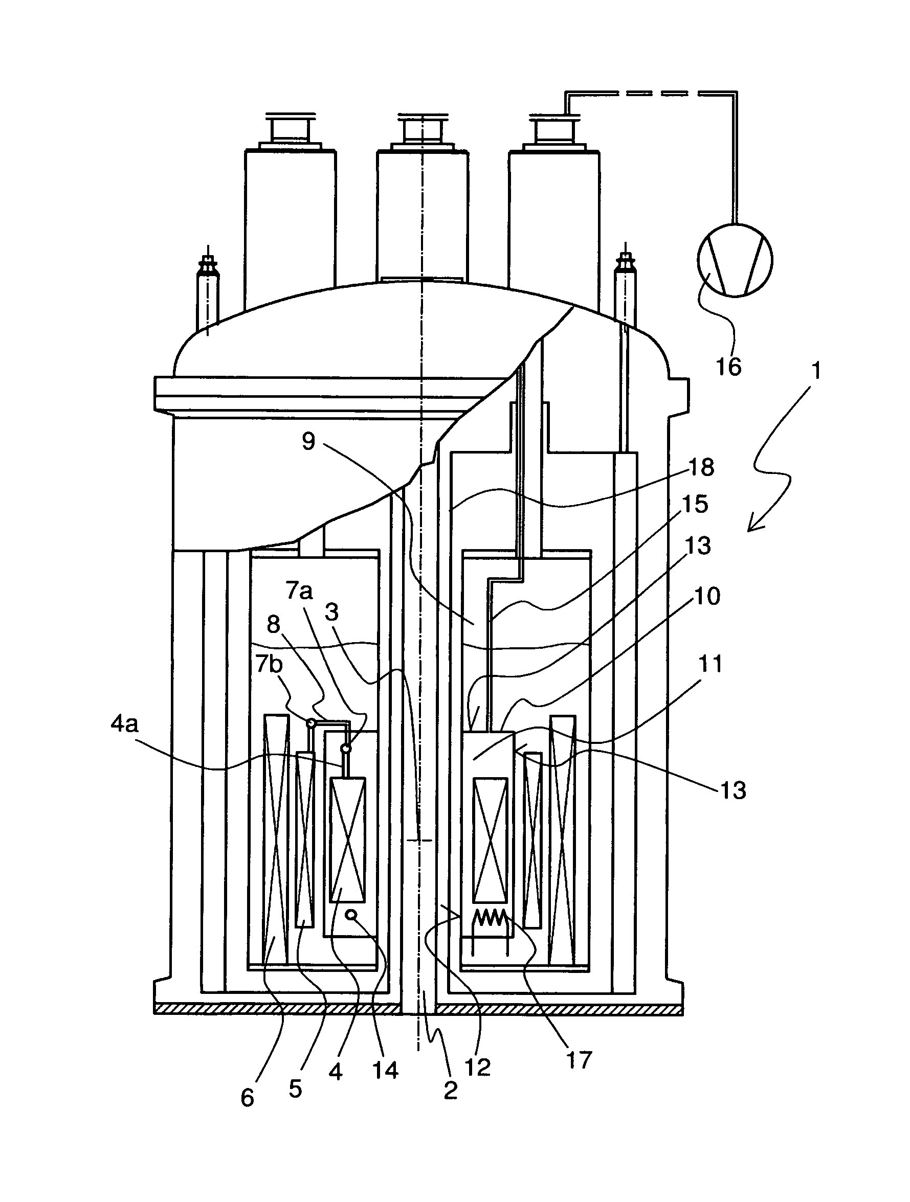
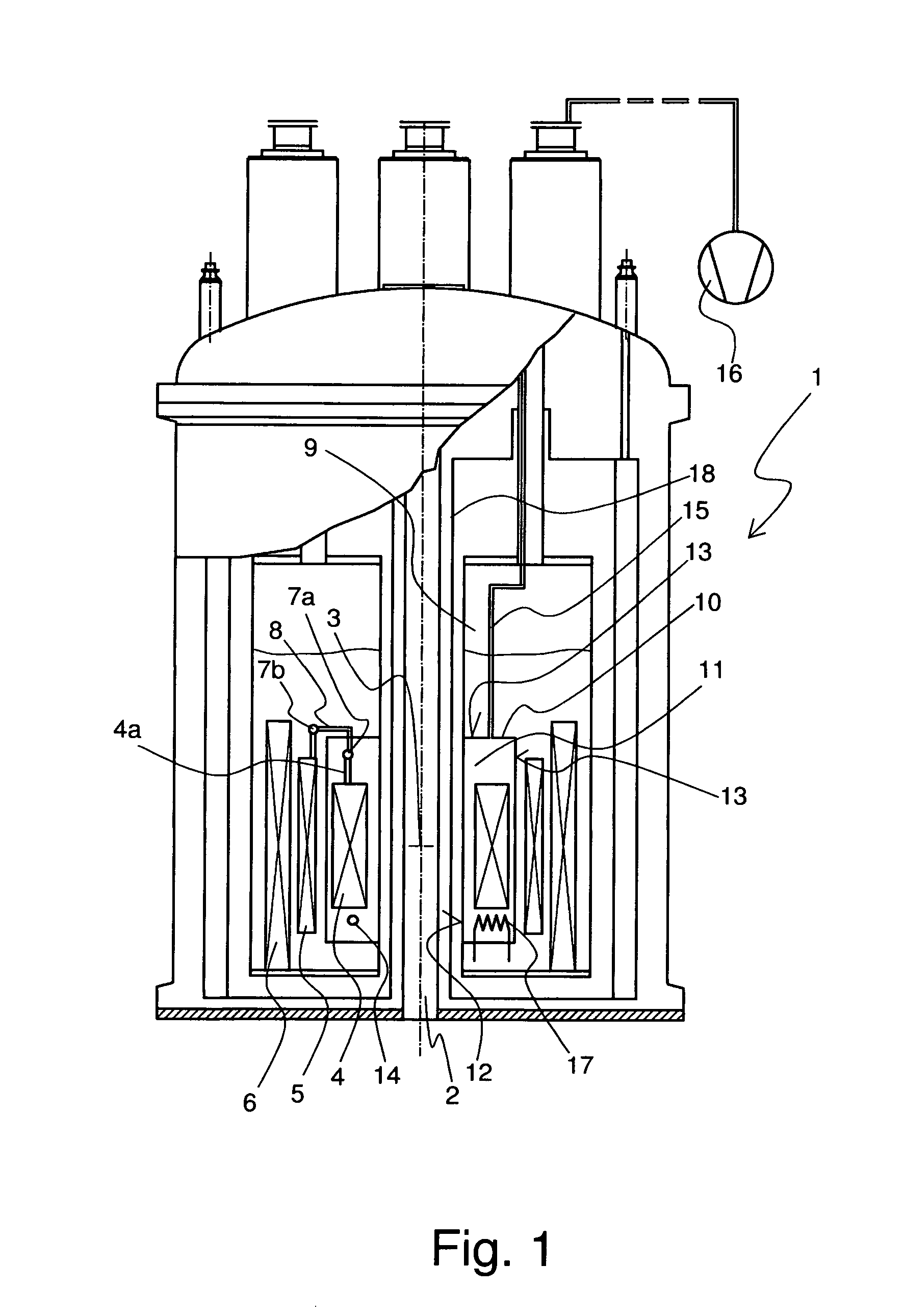
[0035]FIG. 1 shows a cryostat 1 in accordance with the invention. The cryostat 1 has a room temperature bore 2 in which a measuring volume 3 for a sample is provided. The measuring volume 3 is located in the center of a magnetic coil system, which is formed by three solenoid-shaped coil section 4, 5, 6. The radially innermost coil section 4 has a wounding made from high temperature superconductor (HTS). The middle coil section 5 is wound with Nb3Sn wire and the outer most coil section 6 is wound with NbTi wire. The coil sections 5, 6 therefore represent low temperature superconductor (LTS) coil sections. The coil sections 4, 5, 6 are electrically connected to each other in series, as is shown in an exemplary fashion by means of superconducting joints 7a and 7b. At joint 7a, the high HTS material of a lead 4a is connected to a HTS coil section 4 by means of an adaptor section 8 made from NbTi. At joint 7b, the adaptor member 8 is connected to the Nb3Sn wire of the LTS section 5.

[0036...

third embodiment

[0041]FIG. 3 shows a cryostat 1 in accordance with the invention having a lower helium tank 9 and an additional upper helium tank 31. The coil sections 4, 5, 6 of the magnet coil system are located in the lower helium tank 9. The substantially liquid helium disposed therein has a temperature TL of approximately 2 K. A helium-sealed chamber 11 is disposed within the helium tank 9 and contains the HTS coil section 4. If helium is present in the chamber 11, that helium is gaseous and likewise has a temperature of approximately 2 K. The lower helium tank 9 can be filled by openings (not shown) and can be cooled by a cooling device (also not shown: compare e.g. U.S. Pat. No. 5,220,800). The upper helium tank 31 likewise substantially contains liquid helium 32 but at a temperature of 4 K. The helium pressure in the tanks 9 and 31 is approximately 1 bar. The two helium tanks 9, 31 are separated by a vacuum barrier and connected by means of a safety device, in this particular example, an op...


PUM

PropertyMeasurementUnit
external pressureaaaaaaaaaa
pressureaaaaaaaaaa
pressureaaaaaaaaaa

Abstract

A cryostat (1) with a magnet coil system including superconductors for the production of a magnet field B0 in a measuring volume (3) has a plurality of radially nested solenoid-shaped coil sections (4, 5, 6) and which are electrically connected in series, at least one of which being an LTS section (5, 6) with a conventional low temperature superconductor (LTS) and at least one of which being an HTS section (4) including a high temperature superconductor (HTS), wherein the magnet coil system is located in a helium tank (9) of the cryostat (1) along with liquid helium at a helium temperature TL. The apparatus is characterized in that a chamber (11) is provided within which the HTS sections (4) are held having an internal portion with a sufficiently low pressure such that helium located therein at a temperature of TL is gaseous. The cryostat in accordance with the invention can be utilized to maintain HTS coil sections over a long period of time in a reliable fashion.

Description

[0001]This application is the national stage of PCT / EP2007 / 001926 filed on Mar. 7, 2007 and also claims Paris Convention priority to DE 10 2006 012 508.8 filed Mar. 18, 2006.BACKGROUND OF THE INVENTION[0002]The invention concerns a cryostat having a magnetic coil system including superconducting materials for generation of a magnetic field B0 within a measurement volume, the magnet system having a plurality of radially nested solenoid-shaped coil sections connected in series at least one of which is an LTS section of a conventional low temperature superconductor (LTS) and with at least one HTS section of a high temperature superconductor (HTS), wherein the magnet coil system is located in a helium tank of the cryostat having liquid helium at a helium temperature TL.[0003]Cryostats of this kind are e.g. disclosed in DE 10 2004 007 340 A1.[0004]By way of example, nuclear magnetic resonance systems, in particular spectrometers, require very strong, homogenous and stable magnetic fields...

Claims


Application Information

Patent Timeline
Patent Type & Authority Patents(United States)
IPC IPC(8): H01F6/04G01V3/00H01F6/06
CPCG01R33/3815H01F6/06G01R33/3804H01F6/04
Inventor SCHLENGA, KLAUSKLAESER, MARIONARNDT, THOMAS
Owner BRUKER BIOSPIN
Why Eureka
Try Eureka