Production method of stator blade and turbo-molecular pump with the stator blade

a production method and stator blade technology, which is applied in the direction of machines/engines, liquid fuel engines, forging/pressing/hammering apparatuses, etc., can solve the problems of increasing the overall size of the pump, accelerating the increase of fabrication costs, and increasing fabrication costs. , to achieve the effect of increasing the size and increasing the fabrication cos

Inactive Publication Date: 2012-09-04
SHIMADZU CORP
View PDF7 Cites 4 Cited by
  • Summary
  • Abstract
  • Description
  • Claims
  • Application Information

AI Technical Summary

Benefits of technology

[0008]In view of the above circumstances, it is an object of the present invention to provide a method of producing a stator blade for use in a turbo-molecular pump, which is capable of forming a blade element having a desirable configuration, in a simple manner, while suppressing an increase in fabrication cost.
[0013]In the method of the present invention, the laser beam is emitted onto the metal plate at an incident angle oblique to the principal surface of the metal plate. This makes it possible to form a blade element having an upstream edge surface and / or a downstream edge surface extending obliquely to the principal surface of the metal plate, in a simple manner, while suppressing an increase in fabrication cost.
[0014]In addition, a turbo-molecular pump comprising a stator blade produced by the method of the present invention can avoid an increase in size due to the configuration of a blade element.

Problems solved by technology

Thus, each of upper and lower edge surfaces of the obliquely-inclined blade element is positioned to have a chevron shape protruding in the axial direction of the rotor, which leads to a problem about an increase in overall size of the pump.
If a thicker metal plate is used to ensure the rigidity of a stator blade, a fabrication cost will be further increased.
Thus, it is extremely difficult to form all the blade elements by one cycle of punching operation, which will accelerate an increase in fabrication cost.

Method used


Image

  • Production method of stator blade and turbo-molecular pump with the stator blade
  • Production method of stator blade and turbo-molecular pump with the stator blade
  • Production method of stator blade and turbo-molecular pump with the stator blade

Examples


Embodiment Construction

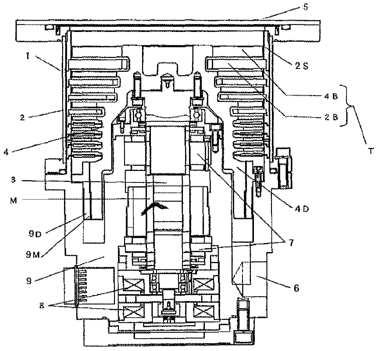
[0023]With reference to the drawings, the present invention will now be specifically described based on the most preferred embodiment thereof. FIG. 1 is a schematic sectional view showing a pump body 1 of a turbo-molecular pump according to one embodiment of the present invention. The turbo-molecular pump comprises the pump body 1 and a controller (not shown) for supplying a power to the pump body 1 to control rotational driving of the pump body 1.

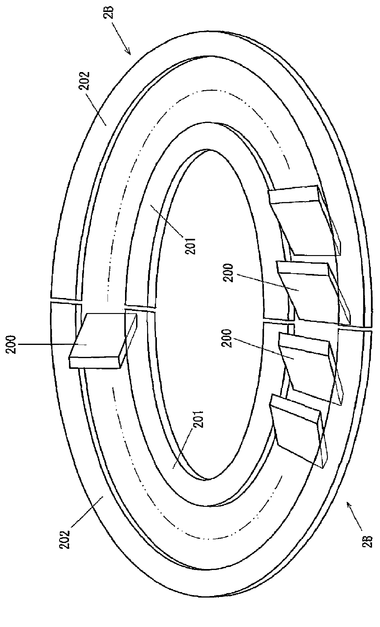
[0024]The pump body 1 includes a casing 2, a rotor 4 disposed inside the casing 2, and a rotary shaft 3 fastened to the rotor 4 using a bolt. The rotary shaft 3 is adapted to be supported by a pair of upper and lower radial magnetic bearings 7 and a thrust magnetic bearing 8, in a non-contact manner, and rotationally driven by a motor M. The rotor 4 is formed with a rotor cylinder 4D and provided with a plurality of rotor blades arranged in a multistage manner. Correspondingly, a plurality of stator blades 2B arranged in a multistage manne...


PUM

PropertyMeasurementUnit
incident angleaaaaaaaaaa
beam angleaaaaaaaaaa
beam angle θ1aaaaaaaaaa

Abstract

Disclosed is a method of producing a stator blade for use in a turbo-molecular pump. The method includes subjecting a metal plate to a slitting process to form a blade element having an upstream edge surface and a downstream edge surface, wherein a laser beam is emitted onto the metal plate at an incident angle oblique to a principal surface of the metal plate. Thus, the upstream edge surface and / or the downstream edge surface can be formed to extend obliquely relative to the principal surface of the metal plate, in a simple manner, while eliminating a need for a burr removal operation which would otherwise be necessary in a punching-based slitting process.

Description

BACKGROUND OF THE INVENTION[0001]1. Field of the Invention[0002]The present invention relates to a method of producing a stator blade for use in a turbo-molecular pump for an evacuation purpose, and a turbo-molecular pump having the stator blade.[0003]2. Description of the Related Art[0004]A turbo-molecular pump designed for a high level of evacuation is provided with a plurality of rotor blades arranged in a multistage manner and a plurality of stator blades arranged in a multistage manner. Each of the rotor blades comprises a plurality of blade elements each formed to extend around an entire circumference of a rotor while protruding from an outer peripheral surface of the rotor. Each of the stator blades comprises a plurality of blade elements each arranged to surround the rotor, wherein each of the blade elements is connected to an arc-shaped strip member at an outer peripheral edge surface and / or an inner peripheral edge surface thereof. Generally, the stator blade in each stage...

Claims


Application Information

Patent Timeline
Patent Type & Authority Patents(United States)
IPC IPC(8): F04D29/44F04D19/04
CPCF04D29/542F04D19/042Y10T29/49329
Inventor OISHI, KOUTA
Owner SHIMADZU CORP
Why Eureka
Try Eureka