
Methods and Apparatuses for Trimming Circuits

a technology of integrated circuits and trimming devices, which is applied in the direction of instruments, measuring devices, apparatuses with stored calibration coefficients, etc., can solve the problems of affecting the performance of the whole micro-fluid ejection heater chip, and the cost associated with making integrated circuits often rises, so as to minimize the cost of fabrication and reduce the cost of making integrated circuits. , the effect of reducing the cost of manufacturing

Inactive Publication Date: 2007-12-13
LEXMARK INT INC
View PDF7 Cites 2 Cited by
  • Summary
  • Abstract
  • Description
  • Claims
  • Application Information

AI Technical Summary

Benefits of technology

[0002]Two common goals in integrated circuit manufacturing are to (1) minimize fabrication costs and (2) make integrated circuits that are capable of tolerating post fabrication processing. The costs associated with making integrated circuits often rises when attempting to improve characteristics such as more accurate voltage and current references, A / D converters, temperature sensing components, pulse extension control components and more stable regulator circuits. Trimming fabricated circuits is known in the art of integrated circuit manufacturing as one means to attempt to minimize these costs. The process of trimming can be described as tuning an output or other function of a circuit after fabrication of that circuit. Circuit trimming can be used, for example, when the output of a circuit falls outside of predetermined tolerance ranges for acceptable circuit performance. Instead of making changes to, for example actual transistors and transistor characteristics in the integrated circuit during fabrication (i.e., increasing fabrication costs), such a circuit may be trimmed so that its output is within the range of tolerance.

Problems solved by technology

The costs associated with making integrated circuits often rises when attempting to improve characteristics such as more accurate voltage and current references, A / D converters, temperature sensing components, pulse extension control components and more stable regulator circuits.
These activities have been shown to shift transistor thresholds, thereby directly affecting the performance of the micro-fluid ejection heater chip as a whole.

Method used


Image

  • Methods and Apparatuses for Trimming Circuits
  • Methods and Apparatuses for Trimming Circuits
  • Methods and Apparatuses for Trimming Circuits

Examples


Embodiment Construction

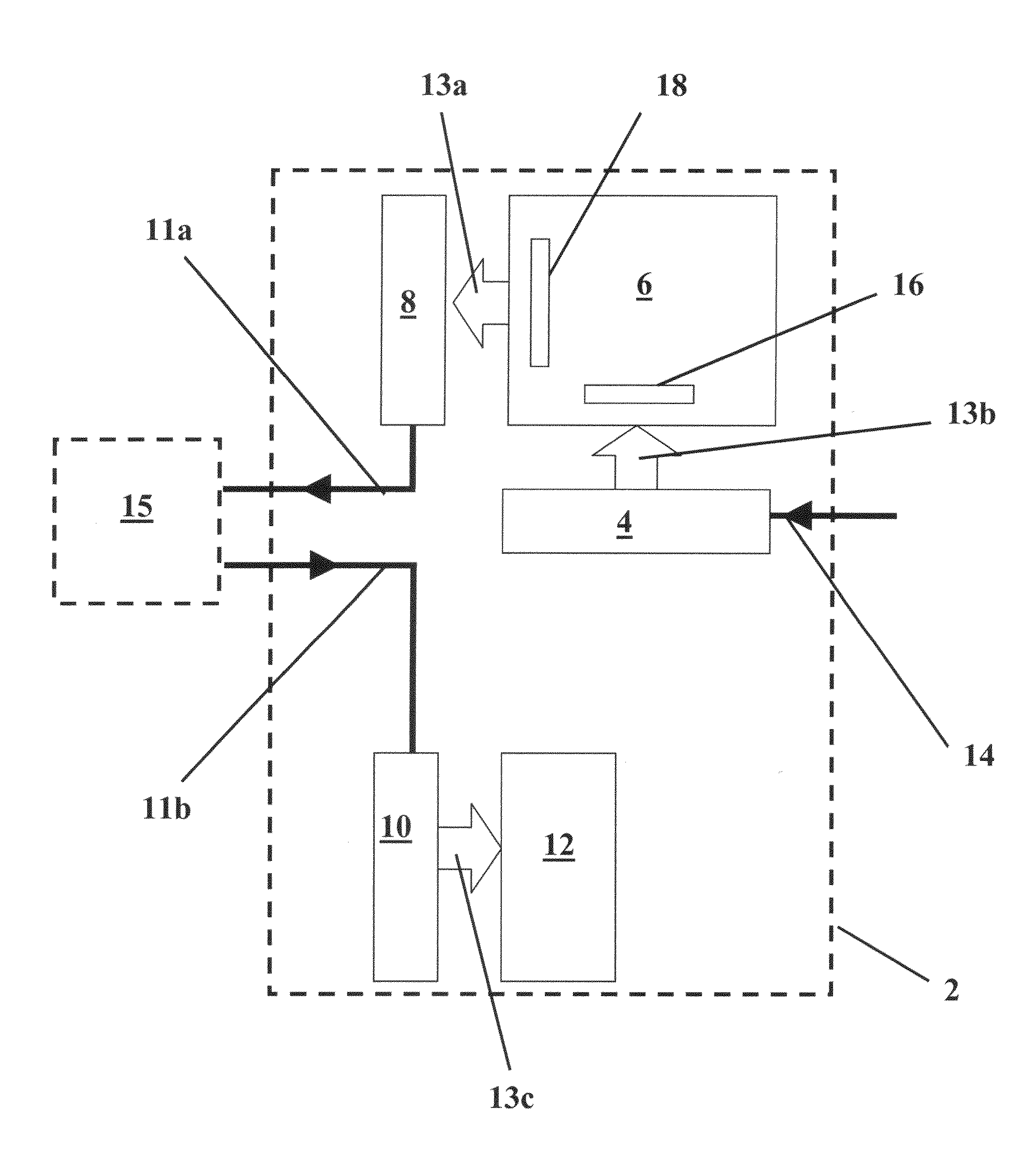
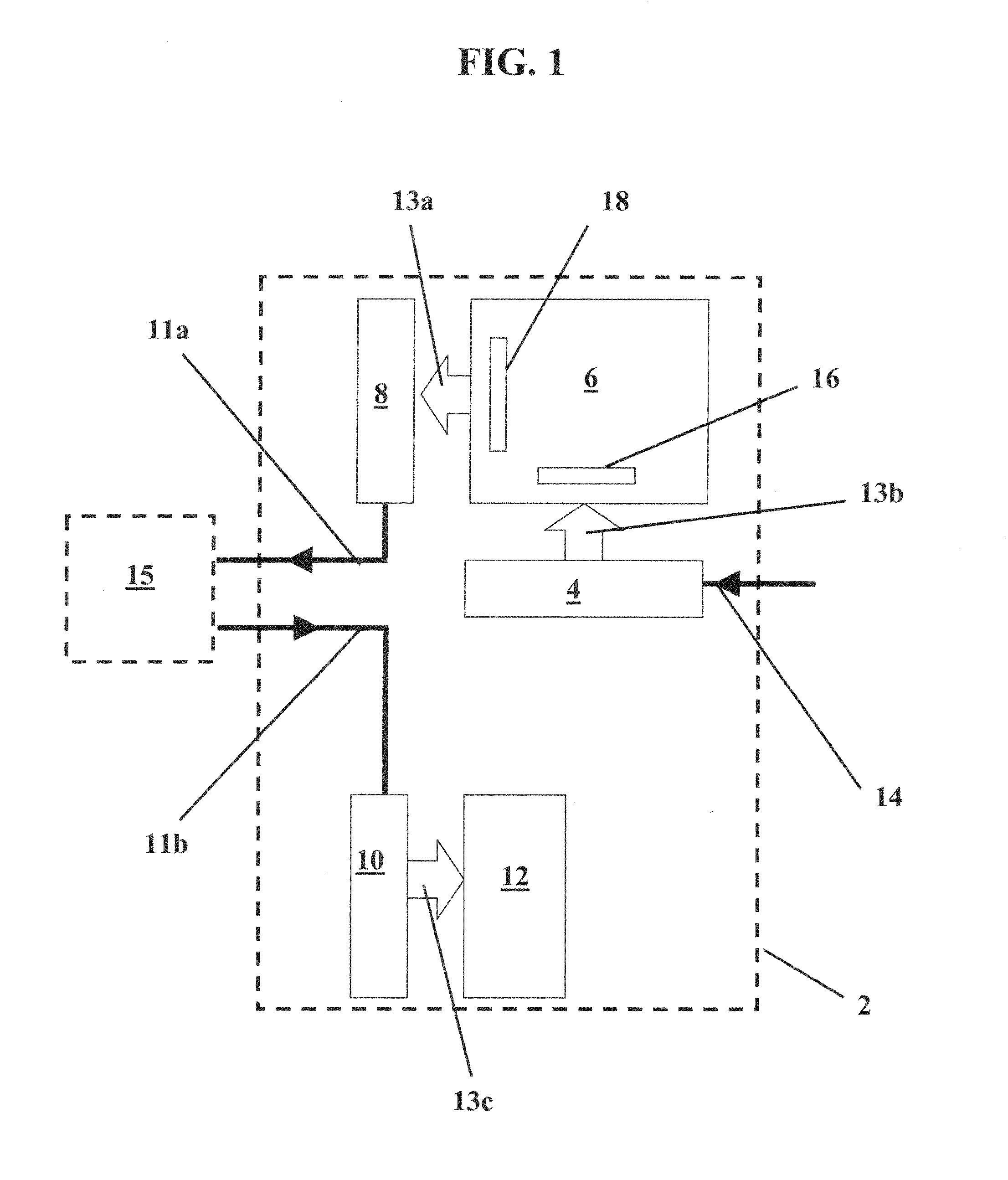
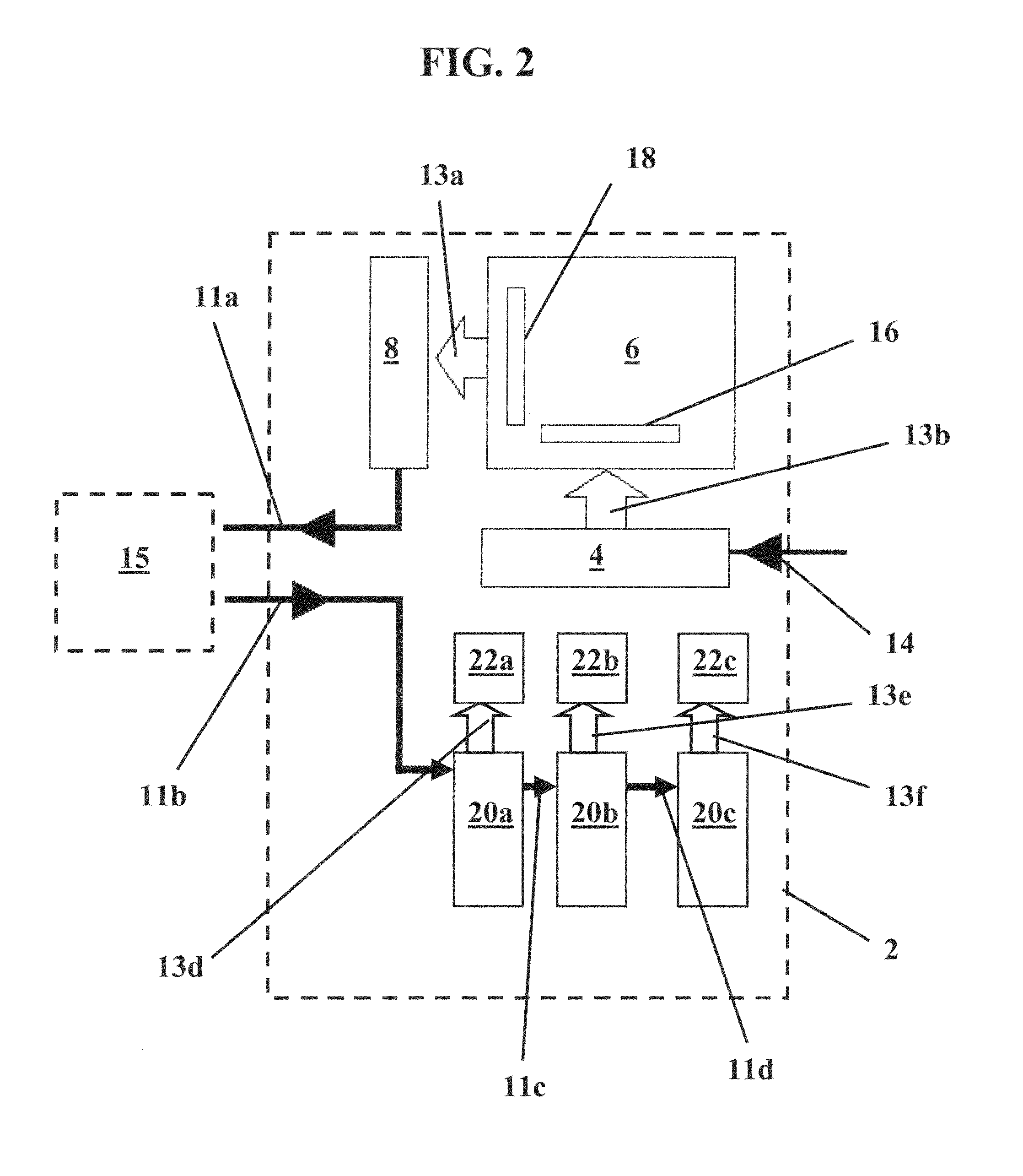
[0013]An overview of an integrated circuit 2 as used in various embodiments of the invention is shown in Figure. The boundaries of the integrated circuit 2 are drawn as dotted lines to show that the parts described hereafter may be arranged in many different formations. Integrated circuit 2 is one exemplary embodiment of many circuit embodiments used with the methods described herein. The integrated circuit 2 includes an address register 4, a memory 6, a serial shift register 8, a serial data register 10, and a trim register 12. Serial lines 11a, 11b, and 14 are designated as solid black arrows and broad / outlined arrows 13a, 13b, and 13c designate parallel lines. However, it should be understood by those skilled in the art that any combination of serial and parallel lines could be used to accomplish the methods described herein, so the choice of serial lines and parallel lines represented in FIG. 1 is not meant to be limiting.

[0014]The address register 4 is capable of receiving inco...


PUM


Abstract

The inventions relate to methods for trimming integrated circuits. Various embodiments include providing a method to trim an integrated circuit wherein trim data is stored in an on-board memory and then sent off of the circuit to be operated on by an external device. Corresponding trim data is then sent back to the integrated circuit in order to potentially modify the function of one or more analog devices along the circuit. Other embodiments include methods for trimming integrated circuits wherein trim data is stored in an on-board memory and retrieved using an on-board sequencer. The retrieved data is used to modify a function of one or more analog devices on the integrated circuit.

Description

FIELD [0001]This invention relates to apparatus and methods for modifying the function of an analog device on an integrated circuit. More particularly in one embodiment, the invention relates to the field of trimmable integrated circuits and methods for trimming integrated circuits.BACKGROUND AND SUMMARY OF THE INVENTION[0002]Two common goals in integrated circuit manufacturing are to (1) minimize fabrication costs and (2) make integrated circuits that are capable of tolerating post fabrication processing. The costs associated with making integrated circuits often rises when attempting to improve characteristics such as more accurate voltage and current references, A / D converters, temperature sensing components, pulse extension control components and more stable regulator circuits. Trimming fabricated circuits is known in the art of integrated circuit manufacturing as one means to attempt to minimize these costs. The process of trimming can be described as tuning an output or other ...

Claims


Application Information

Patent Timeline
Patent Type & Authority Applications(United States)
IPC IPC(8): G01R31/04
CPCG01D18/008
Inventor BERGSTEDT, STEVEN WAYNEEDELEN, JOHN GLENNFISCHER, CARSON ALLEN
Owner LEXMARK INT INC
Learn More