
System and method for wind condition estimation

a technology of wind turbines and wind conditions, applied in wind energy generation, testing/calibration of speed/acceleration/shock measurement devices, liquid fuel engine components, etc., can solve the problem of limited sensor technology and the effect of control systems

Inactive Publication Date: 2012-09-04
GENERAL ELECTRIC CO
View PDF10 Cites 19 Cited by
  • Summary
  • Abstract
  • Description
  • Claims
  • Application Information

AI Technical Summary

Benefits of technology

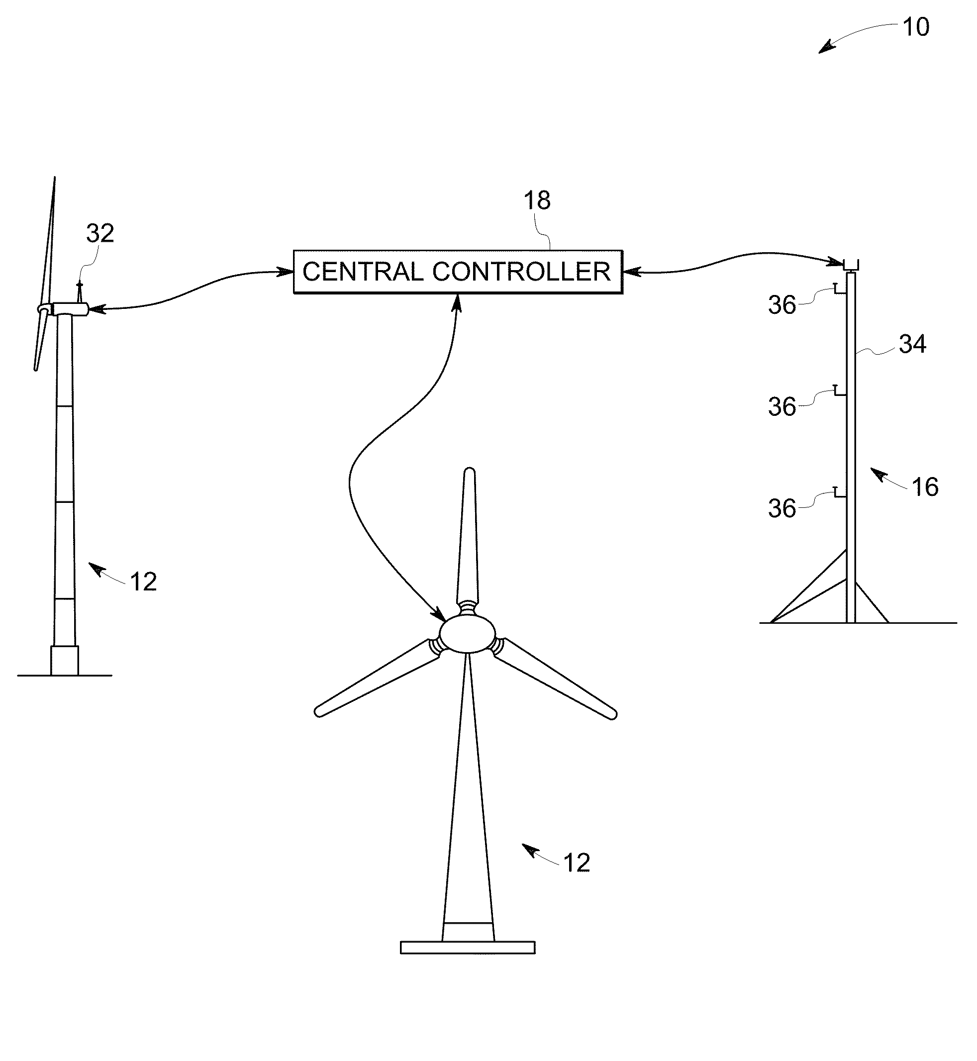
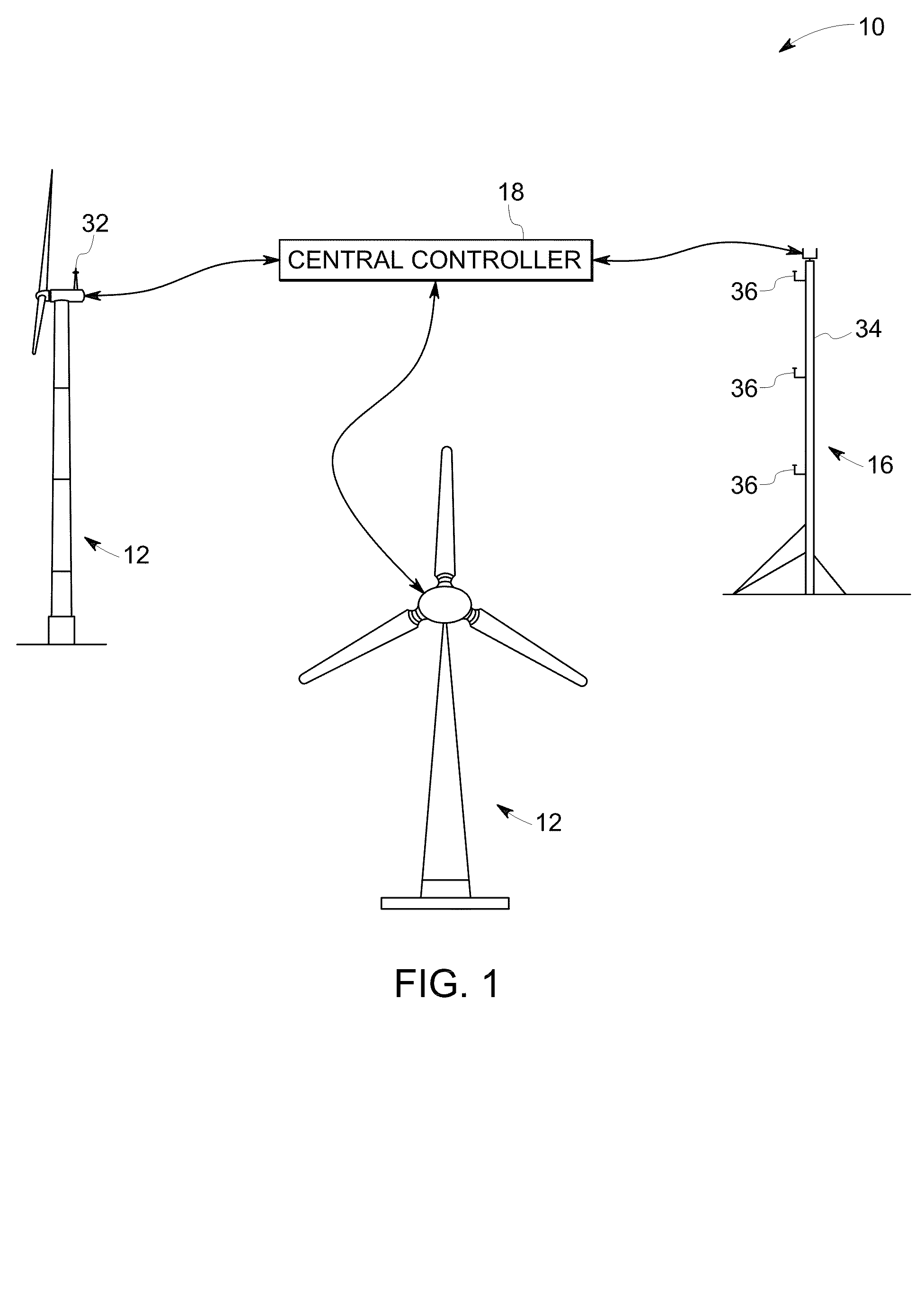
"The patent describes a wind power generation system that uses a measuring device and a sensor to gather wind condition signals at a wind turbine and a test location. These signals are then used to estimate the wind condition at the wind turbine location using a wind correlation database. The system can adjust the wind condition signal at the wind turbine location based on the difference between the actual wind condition and the estimated wind condition. This allows for more accurate wind condition monitoring and control, leading to improved wind power generation efficiency."

Problems solved by technology

However, the effectiveness of these control systems is constrained by limitations on sensor technologies.

Method used


Image

  • System and method for wind condition estimation
  • System and method for wind condition estimation
  • System and method for wind condition estimation

Examples


first embodiment

[0022]At step 106, central controller 18 searches in a wind correlation database for an approximate wind velocity of metmast 16 which is most close to the measured actual metmast velocity {right arrow over (V)}mm. An exemplary wind correlation database 122 is shown in FIG. 4. The correlation database 122 is formulated by simulating the wind blowing to wind farm 10 from a number n of wind directions D with a certain wind speed. The illustrated correlation database 122 includes twelve wind directions D, i.e. n=12, and thus every two adjacent directions are separated by 30 degrees. One example of a certain wind speed is 10 meter per second (“m / s”). At each direction Di with a wind speed of 10 m / s that blows to the wind farm 10, there is a corresponding wind correlation set Mi. Each wind correlation set Mi includes a corresponding wind velocities {right arrow over (V)}mi, and {right arrow over (V)}ti respectively for metmast 16 and wind turbine 12. Each of the wind velocities {right ar...

second embodiment

[0028]a wind correlation database 124 for performing step 106 is shown in FIG. 5. The wind correlation database 124 is formulated by simulating a number n of wind directions D and simulating each direction with a number m of wind speeds S, for example twelve wind directions D and ten wind speeds S, from 5 m / s to 14 m / s in each wind direction D, as illustrated. Each data set Aij, which corresponds to one simulated wind direction Di and one wind speed Sj, includes a wind velocity {right arrow over (V)}mij for metmast 16 and a wind velocity {right arrow over (V)}tij for wind turbine 12. In certain embodiments, each data set Aij, includes a wind velocity {right arrow over (V)}mij for metmast 16 and a plurality of wind velocities {right arrow over (V)}mij for a plurality of wind turbines 12. The velocity correlation database 124 can also be simulated by commercially available software, such as CFX® or Fluent® by ANSYS, Inc.

[0029]Referring to FIGS. 3 and 5, a second embodiment of step 106...


PUM


Abstract

A wind power generation system includes a wind turbine at a wind turbine location, a measuring device for providing a wind condition signal at a test location, a sensor for providing a wind condition signal at the wind turbine, and a controller. The controller is configured for receiving the wind condition signals, using a wind correlation database and the wind condition signal at the test location for providing a wind condition estimation at the wind turbine location, obtaining a difference between the wind condition signal at the wind turbine location and the wind condition estimate at the wind turbine location, and using the difference for adjusting the wind condition signal at the wind turbine location.

Description

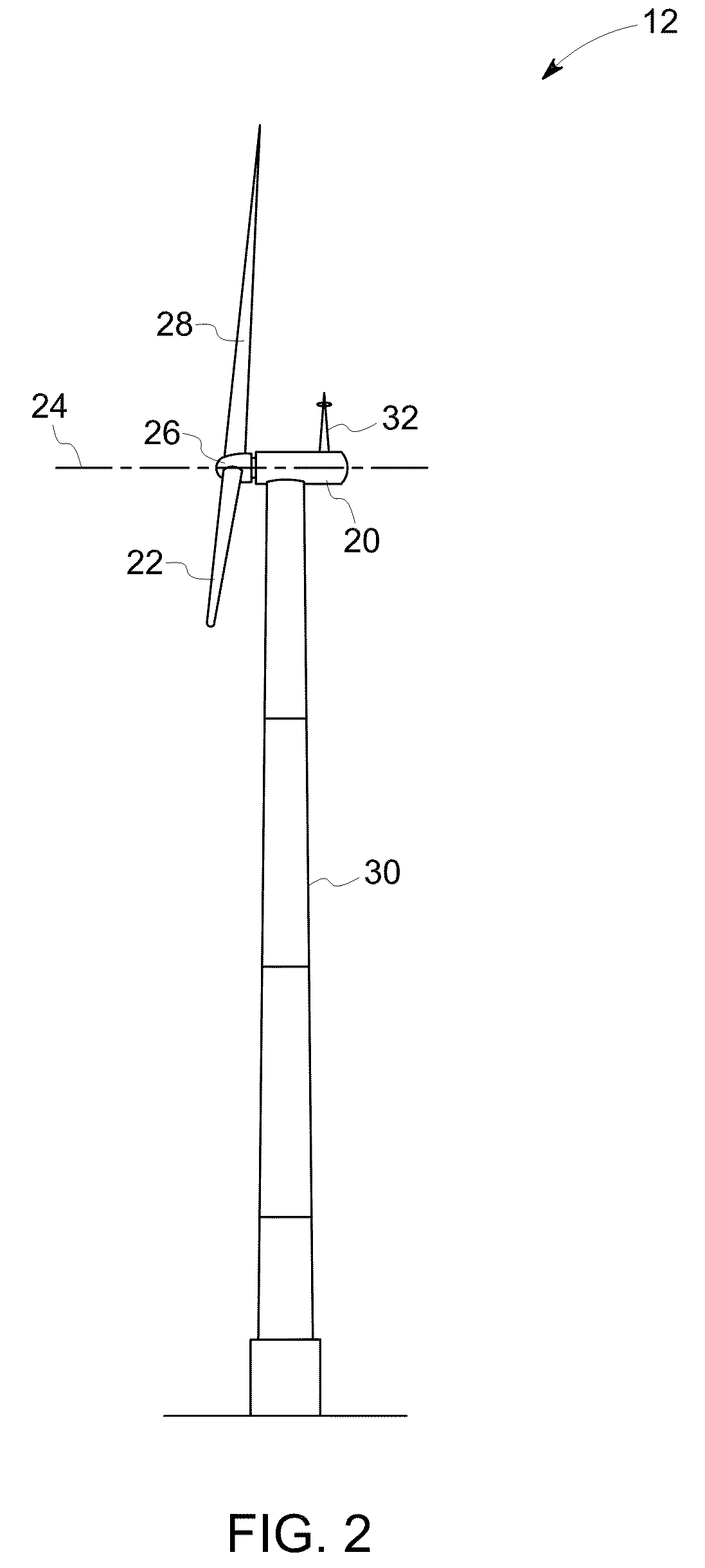
BACKGROUND[0001]The invention relates to systems and methods for estimating wind conditions for wind turbines.[0002]Recently, wind turbines have received increased attention as environmentally safe and relatively inexpensive alternative energy sources. With this growing interest, considerable efforts have been made to develop wind turbines that are reliable and efficient. Generally, a wind turbine includes a rotor having multiple blades. The rotor is mounted to a housing or nacelle, which is positioned on top of a truss or tubular tower. Blades on these rotors transform wind energy into a rotational torque or force that drives one or more generators that may be rotationally coupled to the rotor through a gearbox. The gearbox steps up the inherently low rotational speed of the turbine rotor for the generator to efficiently convert mechanical energy to electrical energy, which is fed into a utility grid. To maximize the efficacy of power generation and to simplify connection to the ut...

Claims


Application Information

Patent Timeline
Patent Type & Authority Patents(United States)
IPC IPC(8): F03D11/00
CPCF03D7/042F03D11/0091F05B2240/96F05B2260/821Y02E10/723F05B2270/32F05B2270/321F05B2270/708Y02E10/722F05B2260/84F03D17/00Y02E10/72
Inventor CHEN, WEIGUOXIA, JIYANGZHAO, LEI
Owner GENERAL ELECTRIC CO
Learn More