Method for mapping of the radio frequency field amplitude in a magnetic resonance imaging system using adiabatic excitation pulses

a magnetic resonance imaging and excitation pulse technology, applied in the field of radio frequency field amplitude mapping in the magnetic resonance imaging system using adiabatic excitation pulses, can solve the problems of spatial non-uniform excitation, non-uniform image intensity and contrast, signal intensity vs. intensity, etc., and achieve the effect of preventing the generation of artefacts

Active Publication Date: 2012-09-04
BRUKER BIOSPIN MRI
View PDF6 Cites 9 Cited by
  • Summary
  • Abstract
  • Description
  • Claims
  • Application Information

AI Technical Summary

Benefits of technology

[0018]The idea underlying this invention is that the B1-sensitivity of the phase of the transverse magnetization generated with adiabatic RF pulses, in particular AFP and AHP pulses, can be employed to map the spatial distribution of B1-intensity. In contrast to conventional radio frequency (RF) pulses, the inventive method establishes a rather strong dependency of the phase in the complex image on the B1 intensity. Even small inhomogeneities in the B1 field distribution can be measured with good accuracy and over a wide range of B1 values.
[0033]Preferred is further a variant wherein the B1 magnitude image is used to determine parameters controlling the RF transmission in an MRI apparatus. In particular, the B1 map can be the basis for calculating the power and / or other properties of an rf transmission pulse or pulse sequence used for imaging of a sample, thus preventing the generation of artefacts from the beginning.

Problems solved by technology

However, due to design imperfections and due to the electromagnetic properties of the object being imaged, the effective RF field is not uniform, leading to a spatially non-uniform excitation.
This, in turn, leads to non-uniform image intensity and contrast.
The drawback of these methods is that the signal intensity vs.
B1 relation is rather complex and depends on relaxation properties of the object, which are spatially non-uniform and may falsify the result.
This dependence has been regarded as an unwanted effect since it may cause a cancellation of signals emitted from different object positions.

Method used


Image

  • Method for mapping of the radio frequency field amplitude in a magnetic resonance imaging system using adiabatic excitation pulses
  • Method for mapping of the radio frequency field amplitude in a magnetic resonance imaging system using adiabatic excitation pulses
  • Method for mapping of the radio frequency field amplitude in a magnetic resonance imaging system using adiabatic excitation pulses

Examples


Embodiment Construction

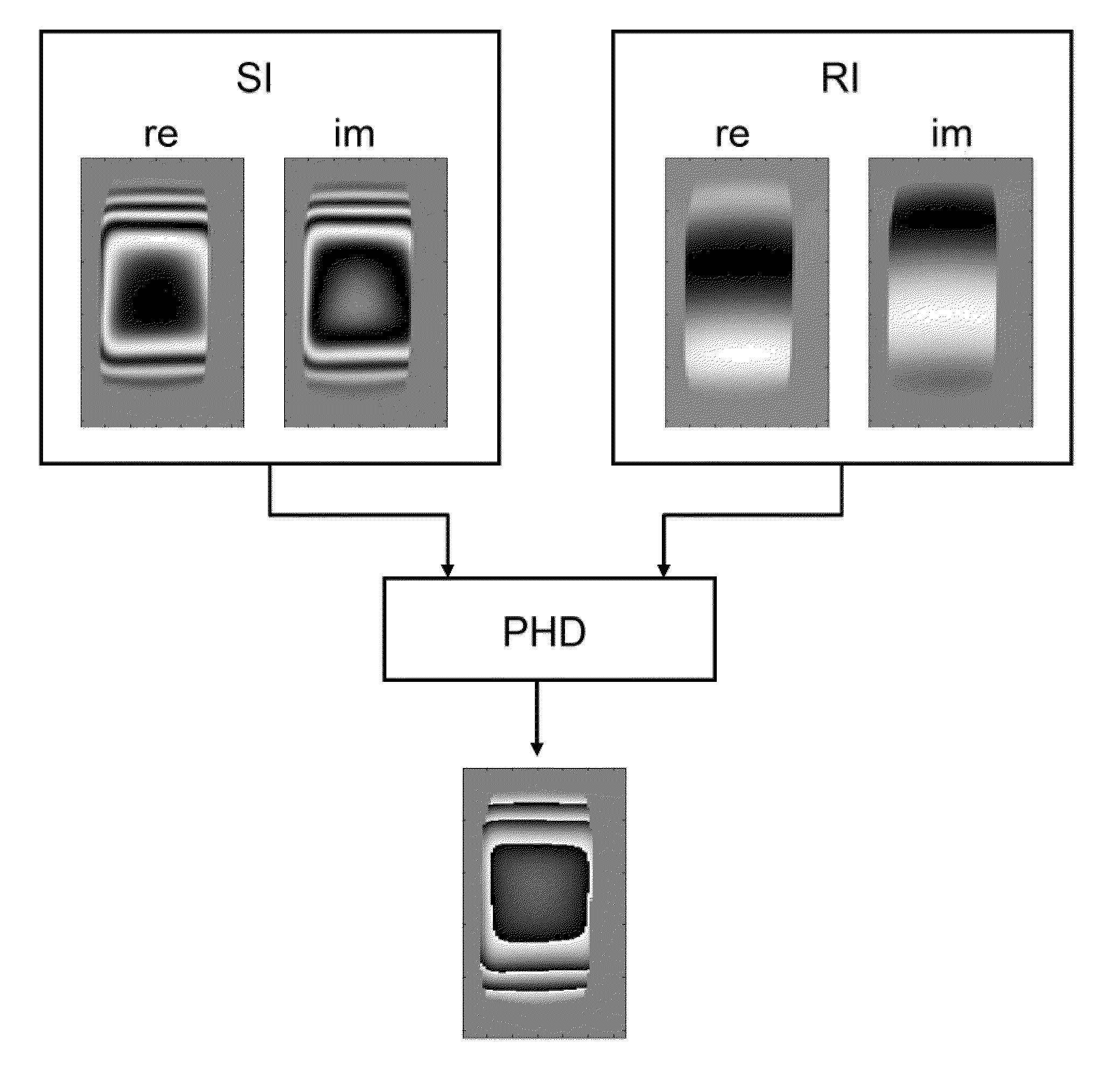
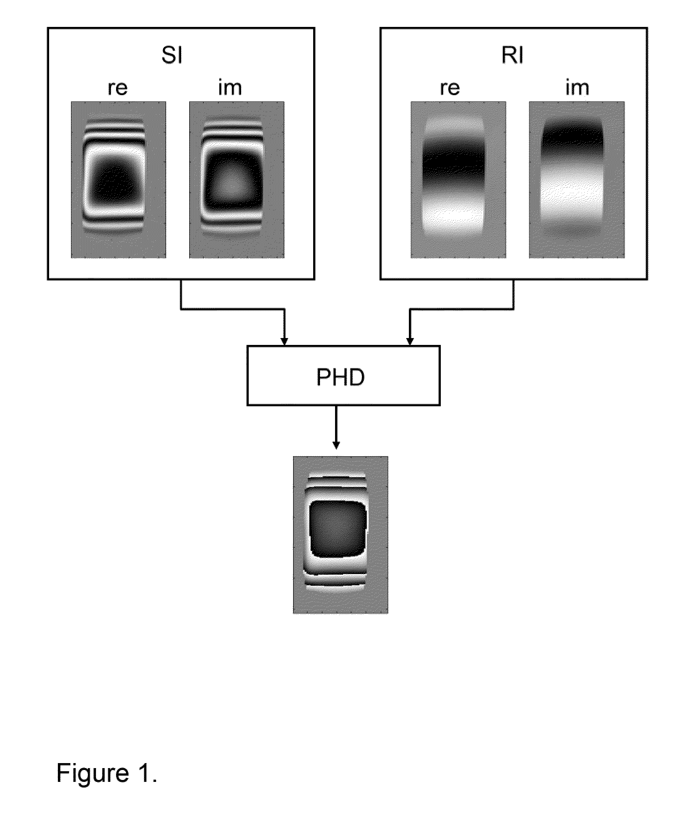
[0043]A method to measure maps of the radio-frequency field (B1) in magnetic resonance imaging (MRI) devices is disclosed. The method is based on an MRI experiment in which a complex image is generated using one or more adiabatic radio-frequency pulses in such a way that the phase of the complex image elements depends on the amplitude of the B1 field. Additional, B1-independent components of the phase may be removed by comparison with reference images. Possible embodiments of the invention include the acquisition of a gradient echo produced with an adiabatic half-passage pulse, acquisition of a spin echo produced by an adiabatic full-passage pulse, and fast spin echo acquisition using a train of adiabatic full-passage pulses.

Adiabatic Pulses

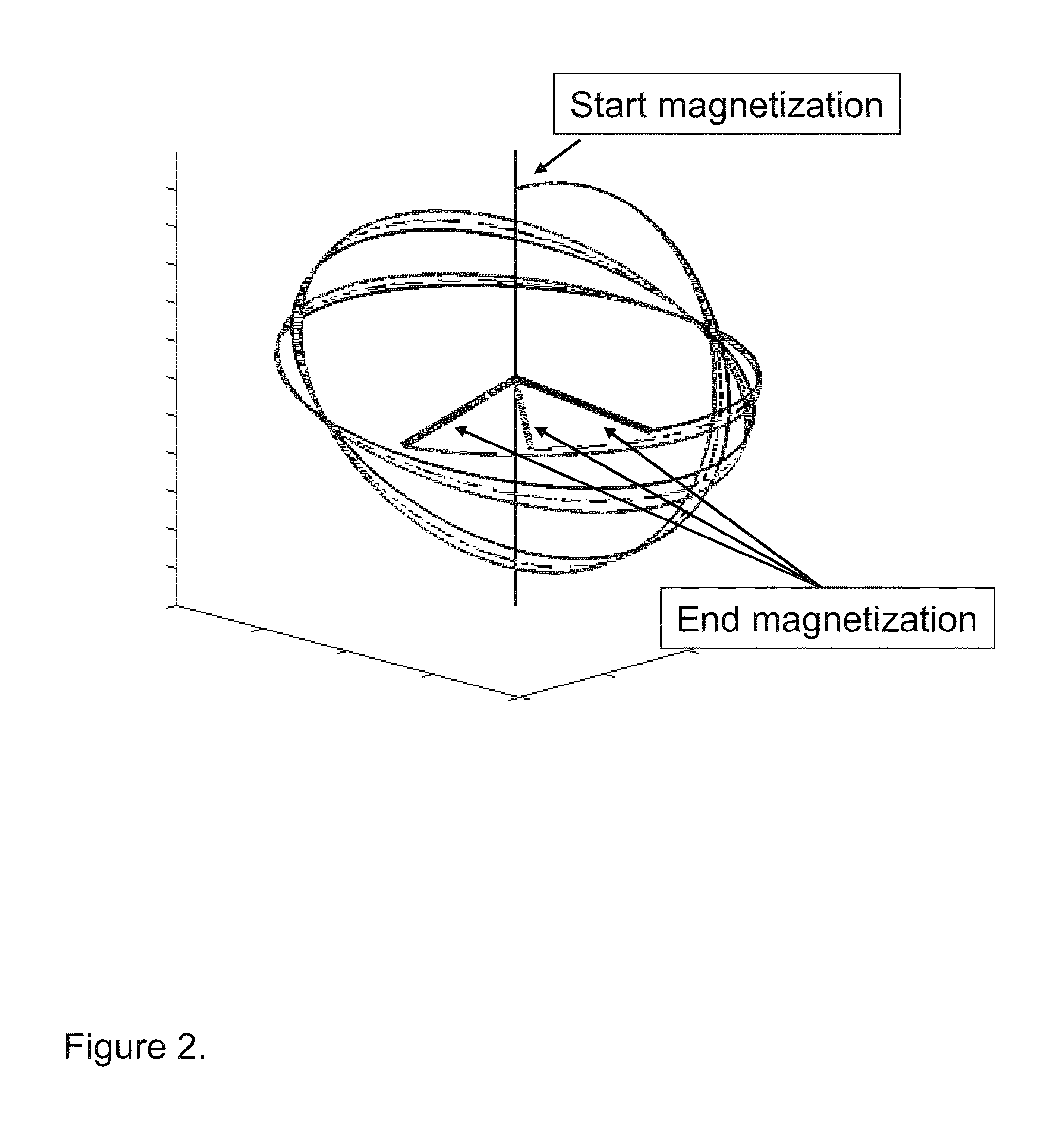
[0044]An adiabatic pulse can be described by two driving functions: B1(t) giving the amplitude of the transverse magnetic field in time, and Δω(t)=ωRF(t)−ω0 giving the deviation of the instantaneous transmitter frequency ωRF(t) from the resonance...


PUM


Abstract

A method for determining the spatial distribution of the magnitude of the radio frequency transmission field B1 in a magnetic resonance imaging apparatus, wherein the method comprises performing an MRI experiment in which a B1-sensitive complex image (SI) of a sample is obtained, wherein the phase distribution within the B1-sensitive complex image (SI) depends on the spatial distribution of the magnitude of the field B1. For establishing the dependency of the phase distribution within the B1-sensitive complex image (SI) on the spatial distribution of the field B1, one or more adiabatic RF pulses are applied. The method provides a simple procedure for mapping the B1 field of a magnetic resonance imaging apparatus with an improved accuracy and a wider measurement range.

Description

[0001]This application claims Paris Convention priority of EP 09 003 853.0 filed Mar. 18, 2009 the complete disclosure of which is hereby incorporated by reference.BACKGROUND OF THE INVENTION[0002]The invention relates to a method for determining the spatial distribution of the magnitude of the radio frequency (=RF) transmission field B1 in a magnetic resonance imaging (=MRI) apparatus, wherein the method comprises performing an MRI experiment in which a B1-sensitive complex image, with a real part and an imaginary part, of a sample is obtained, wherein the phase distribution, with the phase determined by the arc tangent function, within the B1-sensitive complex image depends on the spatial distribution of the magnitude of the field B1.[0003]Such a method is known from U.S. Pat. No. 6,268,728 B1, see Ref. [3].[0004]In a MRI (=Magnetic Resonance Imaging) apparatus, the signal used for image reconstruction is generated by the component of the nuclear magnetization that is transverse r...

Claims


Application Information

Patent Timeline
Patent Type & Authority Patents(United States)
IPC IPC(8): G01R33/44G01V3/00
CPCG01R33/246G01R33/446G01R33/583G01R33/5617
Inventor HENNEL, FRANCISZEK
Owner BRUKER BIOSPIN MRI
Why Eureka
Try Eureka