

Synthetic aperture radar hybrid-quadrature-polarity method and architecture for obtaining the stokes parameters of radar backscatter
a hybrid-quadrature-polarity, radar backscatter technology, applied in the direction of reradiation, measurement devices, instruments, etc., can solve the problems of inability to assume the orientation of the backscatterer prior to the actual use, invoking all of the attendant disadvantages, etc., to minimize the sensitivity to relative errors, less rf hardware, and simple system
- Summary
- Abstract
- Description
- Claims
- Application Information
AI Technical Summary
Benefits of technology
Problems solved by technology
Method used
Image

Examples
Embodiment Construction
[0002]This invention was made with Government support under Department of the Navy contract N00024-03-D-6606. The Government has certain rights in the invention.
BACKGROUND OF THE INVENTION
[0003]1. Field of the Invention
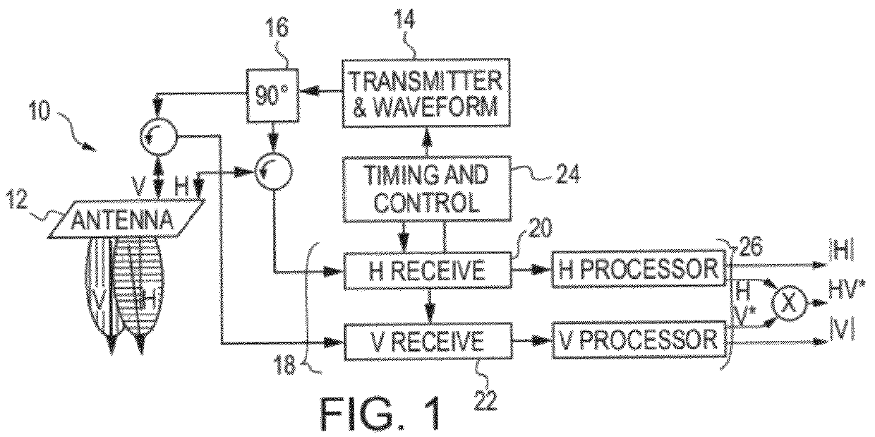
[0004]The present invention relates generally to synthetic aperture radar (SAR) and, more particularly, to a method and architecture to maximize the measurement potential of a SAR using a unique polarimetric scheme for obtaining the Stokes parameters of the radar backscatter.
[0005]2. Description of the Related Art
[0006]In many applications using space-based synthetic aperture radar (SAR), the prime objective is to maximize the measurement potential thereof in response to backscatter from a random field whose elements have unknown orientation relative to the polarity of the radar's illumination. Measurement potential is maximized, if and only if, the data products are the Stokes parameters of the backscattered field (or their logical equivalent) (see R. K. Raney, “Dual...
PUM
 Abstract
Description
Claims
Application Information