
Reciprocating tool

a reciprocating tool and tool body technology, applied in the field of reciprocating tools, can solve the problems of high risk, inconvenient use, and inability to use reciprocating power tools without significant risk of cutting or impacting materials, and achieve the effect of improving the operation of tools and accessories

Inactive Publication Date: 2012-09-11
HENRICKSON ERIK P
View PDF46 Cites 16 Cited by
  • Summary
  • Abstract
  • Description
  • Claims
  • Application Information

AI Technical Summary

Benefits of technology

"The present invention provides an arcuate action reciprocating tool that allows a user to access a work material with a reciprocating accessory, such as a cutting blade, in a more efficient and safe manner. The tool converts linear motion into arcuate motion, allowing the accessory to move in a curved path and enhance the operation. The accessory can be a saw blade, brush, or file, and the tool can be used on convex or round work materials. The invention also provides an elongated support bumper for the tool, and a method for fabricating a saw blade with angled cutting surfaces. Overall, the invention improves the efficiency and safety of the user's work."

Problems solved by technology

Frequently, such as when a work material, such as a pipe, is adjacent one or more materials that are not to be cut or damaged, such as another pipe or wiring, a reciprocating power tool cannot be used without significant risk of cutting or impacting the material that is not to be cut or damaged.
Typical reciprocating power tools are also not well-suited for tasks such as cutting materials, such as boards, which abut a substrate that should not be cut, such as a floor or ceiling.
In some cases, the risk may be high due to the reciprocating tool's and / or an operator's restricted access to the work material, such as when the work material is inside or adjacent a wall.

Method used


Image

  • Reciprocating tool
  • Reciprocating tool
  • Reciprocating tool

Examples


Embodiment Construction

Overview

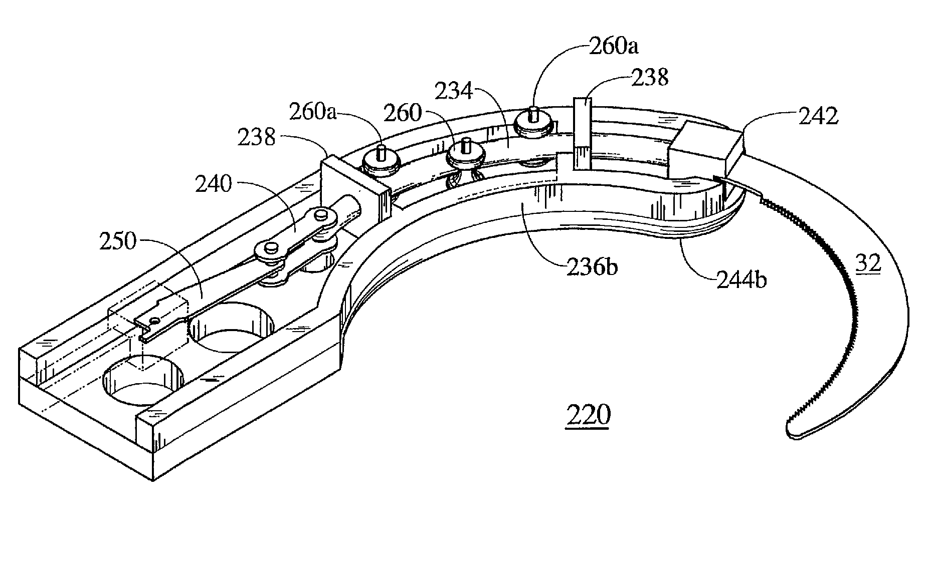
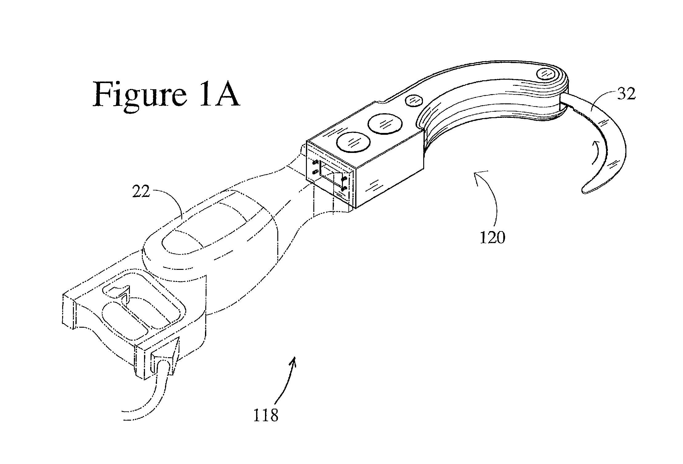
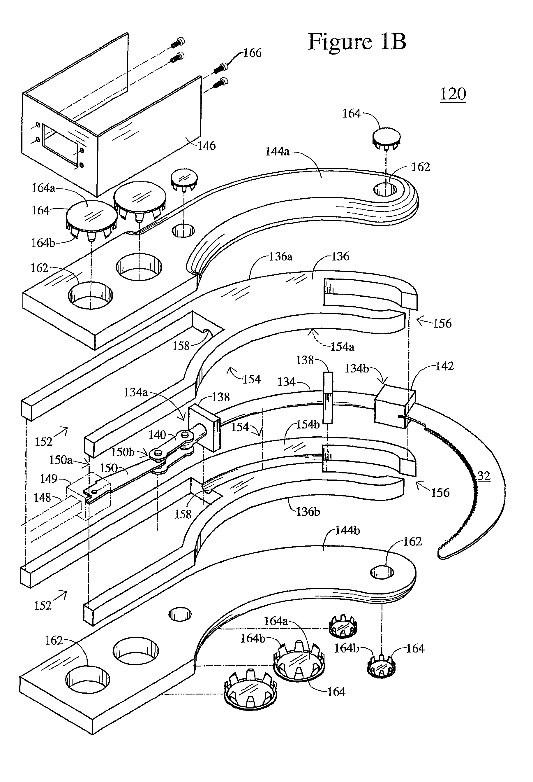
[0077]An arcuate action tool attachment converts a driver input, such as a linear reciprocating driver input, or a rotary or rotational driver input, into arcuate reciprocating motion of an accessory. The arcuate action tool attachment may be attached to a powered drive device that is electrically or battery powered to drive an accessory or saw blade attached thereto. For example, the powered drive device may comprise a linear reciprocating device that linearly drives or reciprocates a driver attached thereto, such as shown in the illustrated embodiment of FIGS. 1A-1D. Such a linear reciprocating device may comprise any power tool, typically electrically powered or battery powered, that produces linear reciprocating motion, such as a reciprocating saw or similar device. Such a linear reciprocating device typically includes a chuck or tool holder adapted to receive a saw blade, for example.

[0078]Optionally, the arcuate action tool attachment may comprise a rotationally driven...


PUM

PropertyMeasurementUnit
angleaaaaaaaaaa
radius of curvatureaaaaaaaaaa
radii of curvatureaaaaaaaaaa

Abstract

An arcuate action tool attachment is adapted to receive an input and to convert that input into reciprocating output motion along an arcuate path. The tool may be adapted to be combined with an existing linear reciprocating device or a rotary device, or the tool may comprise a single unit including a linear reciprocating device or a rotary device. The tool may be fitted with one or more curved or arc-shaped accessories, such as saw blades or the like, that reciprocate along the arcuate paths that may have substantially the same radius of curvature as the accessory.

Description

CROSS REFERENCE TO RELATED APPLICATION[0001]The present application claims the benefit of U.S. Provisional Application Ser. No. 60 / 897,170, filed Jan. 24, 2007, which is hereby incorporated herein by reference in its entirety.FIELD OF THE INVENTION[0002]The present invention relates generally to a reciprocating tool, and, more particularly, to a powered reciprocating tool that reciprocally drives an accessory, such as a cutting blade.BACKGROUND OF THE INVENTION[0003]Reciprocating power tools are typically used for cutting tasks, such as cutting wood, pipe, and other materials more quickly than can normally be accomplished by hand. Reciprocating power tools typically have a tool holder or “chuck” for mounting a straight saw blade, such that the tool holder and saw blade reciprocate linearly relative to the power tool and the material being cut.[0004]Frequently, such as when a work material, such as a pipe, is adjacent one or more materials that are not to be cut or damaged, such as a...

Claims


Application Information

Patent Timeline
Patent Type & Authority Patents(United States)
IPC IPC(8): B23D49/11
CPCB23D45/003B27B19/006B23D57/00B23D67/04B23D67/12B24B23/04B25F3/00A61B17/148B23D45/08A61B17/141A61B17/1624A61B17/1637A61B17/1659A61B2017/320028A61B17/14A61B17/144B23D51/16
Inventor HENRICKSON, ERIK P.
Owner HENRICKSON ERIK P
Learn More