
Systems and methods for measuring a fluid level within a well

a technology of fluid level and well, applied in the field of oil and gas production techniques, can solve the problems of preventing (or even stopping) production into the well, and achieve the effect of accurate gas allocation

Active Publication Date: 2012-09-11
GREENSHOT LLC
View PDF17 Cites 10 Cited by
  • Summary
  • Abstract
  • Description
  • Claims
  • Application Information

AI Technical Summary

Benefits of technology

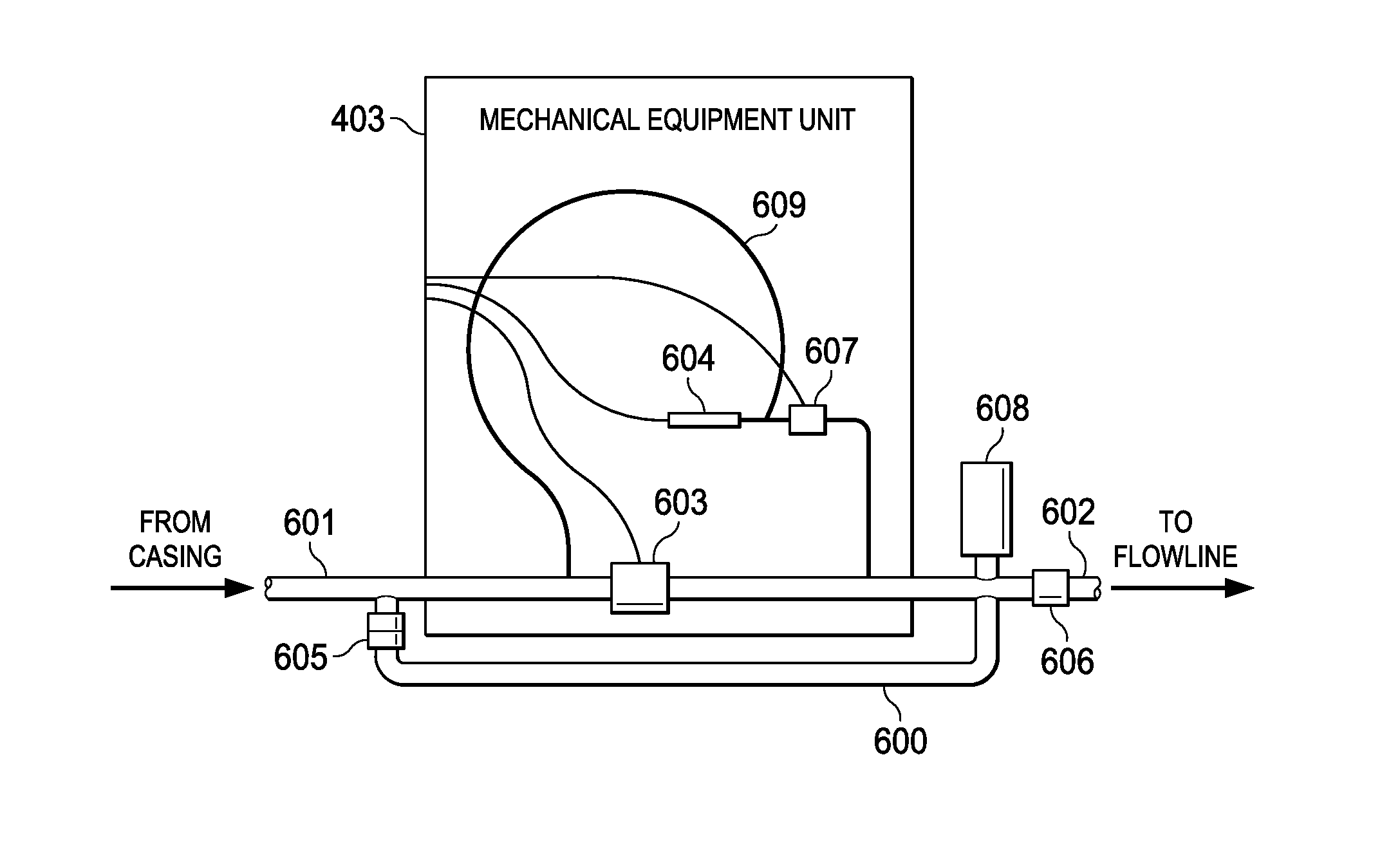
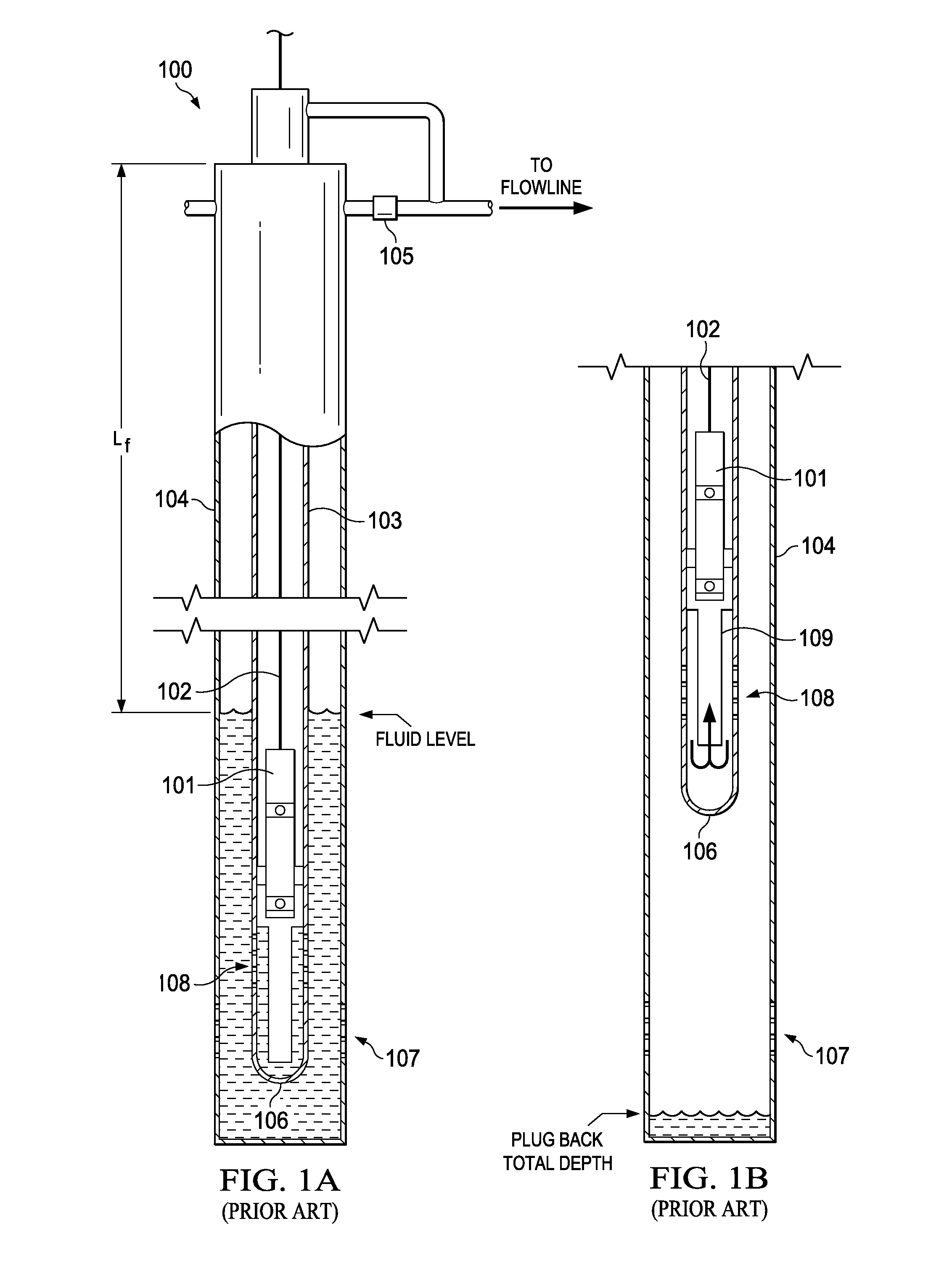
[0017]Embodiments of the present principles provide for systems and methods that allow for a more accurate allocation of gas between wells in multiple-well facilities. To this end, these embodiments allow for the gas production through the annulus of a well to be inferred with reasonable precision. Additionally, the principles of the present invention provide multiple methods of measuring the speed of sound, which can be particularly useful in measuring fluid levels within oil and gas wells. Advantageously, these methods of measuring fluid levels are “green”, since they do not involve injection of foreign substances into the well or emitting gas from it into the atmosphere. The information obtained from the application of the principles of the invention is useful in continuous testing of individual wells, troubleshooting well problems and allocating gas from individual wells for reserve determination and division of cost and revenue.

Problems solved by technology

Without lifting liquid to the surface by external means, back pressure is exerted on the reservoir which impedes (or even stops) production into the well.

Method used


Image

  • Systems and methods for measuring a fluid level within a well
  • Systems and methods for measuring a fluid level within a well
  • Systems and methods for measuring a fluid level within a well

Examples


Embodiment Construction

[0046]The principles of the present invention and their advantages are best understood by referring to the illustrated embodiment depicted in FIGS. 1-19 of the drawings, in which like numbers designate like parts.

[0047]In oil and gas wells, the production stream is separated into volumes of oil, water and gas. The oil and gas components are measured and sold. The water is disposed-of unless it is suitable for agricultural or human use. Measurement of gas is most commonly done with orifice meters. In the United States, gas measurement is guided by the American Gas Association (AGA). A carefully machined orifice plate is placed in the gas stream in a meter run. The meter run is designed to minimize turbulence in the line to increase accuracy of the measurement. Gas pressure upstream of the orifice plate is measured along with differential pressure across the orifice plate. Temperature of the gas in the flow stream is also measured. Also, gas specific gravity (SG) determined from a gas...


PUM


Abstract

A method of determining a fluid level in a well space without substantial venting of gas to the atmosphere or injecting a gas at high pressure. Gas being produced by the well is used to create a pressure differential between two spaces. A wave is induced in the well space by causing the two spaces to come into gaseous communication for a selected time internal. Pressure changes are measured as the induced wave travels through the gas in the well space from the measurement system to a fluid surface and back to the measurement system to determine a round trip travel time of the wave. The fluid level is calculated from the round-trip travel time and a speed of the wave as one-half of the product of the wave speed and the round-trip time.

Description

CROSS-REFERENCE TO RELATED APPLICATION[0001]The present application is a divisional of U.S. patent application Ser. No. 12 / 932,396, filed Feb. 24, 2011, and claiming the benefit of U.S. Provisional Application Ser. No. 61 / 398,933, filed Jul. 2, 2010.FIELD OF INVENTION[0002]The present invention relates in general to oil and gas production techniques and in particular to systems and methods for inferring gas production in oil and gas wells.BACKGROUND OF INVENTION[0003]Natural gas produced from subterranean wells has long been an important source of energy and raw material. Natural gas is a clean burning fuel and is particularly applicable for household use and the generation of electricity. It can also be liquefied and used for powering land, seaborne and airborne vehicles. In its role as a raw material, it is commonly converted into fertilizer and a multiplicity of petrochemical products including plastics. At this writing it is abundant in the United States and figures prominently ...

Claims


Application Information

Patent Timeline
Patent Type & Authority Patents(United States)
IPC IPC(8): E21B21/08
CPCE21B47/10E21B49/00E21B49/087
Inventor GIBBS, SAM GAVINNOLEN, KENNETH BERNARD
Owner GREENSHOT LLC
Learn More