Adjustable magnetic target

a magnetic target and adjustment technology, applied in the field of magnetic proximity switches, can solve the problems of difficult manufacturing, high cost, and significant drawbacks of radially-magnetized smco magnets, and achieve the effect of reducing the longitudinal distan

Active Publication Date: 2012-09-11
GENERAL EQUIP & MFG COMPANY INC D B A TOPWORX
View PDF9 Cites 3 Cited by
  • Summary
  • Abstract
  • Description
  • Claims
  • Application Information

AI Technical Summary

Benefits of technology

[0016]In accordance with one more exemplary aspect of the present invention, a method of simulating the magnetic flux field of a radially-magnetized permanent magnet using two axially-magnetized permanent magnets includes the step of providing an axially-magnetized first permanent magnet having a first pole, a second pole, and a first magnetic flux field. An axially-magnetized second permanent magnet having a first pole, a second pole, and a second magnetic flux field is also provided. The first permanent magnet and the second permanent magnet are positioned such that a longitudinal axis of the first permanent magnet is substantially coaxial with a longitudinal axis of the second permanent magnet, and the first pole of the first permanent magnet is proximate to the first pole of the second permanent magnet. The first permanent magnet and the second permanent magnet are separated by a longitudinal distance. A mechanism to reduce the longitudinal distance between the first permanent magnet and the second permanent magnet is provided, thereby causing the first magnetic flux field of the first permanent magnet to extend away from a longitudinal axis of the first permanent magnet and the second magnetic flux field of the second permanent magnet to extend away from a longitudinal axis of the second permanent magnet.

Problems solved by technology

However, there may be significant drawbacks to the use of radially-magnetized SmCo magnets.
Specifically, radially-magnetized SmCo magnets are difficult, and expensive, to manufacture.
While traditional magnets are cheap and simple to produce, such magnets have relatively weak magnetic flux fields that are unable to be detected when a barrier, such as a pressure vessel wall, separates the magnet from the sensor.
The flux fields of such magnets are also longitudinally non-uniform, and therefore a slight rotation of the magnet relative to a stationary sensor could render the target undetectable to the sensor.
One skilled in the art would recognize that a sensor must be relatively close to an axially-magnetized SmCo magnet to detect such a flux field, making such a magnet unsuitable for applications that require a relatively large distance between the sensor and the target.

Method used


Image

  • Adjustable magnetic target
  • Adjustable magnetic target
  • Adjustable magnetic target

Examples


Embodiment Construction

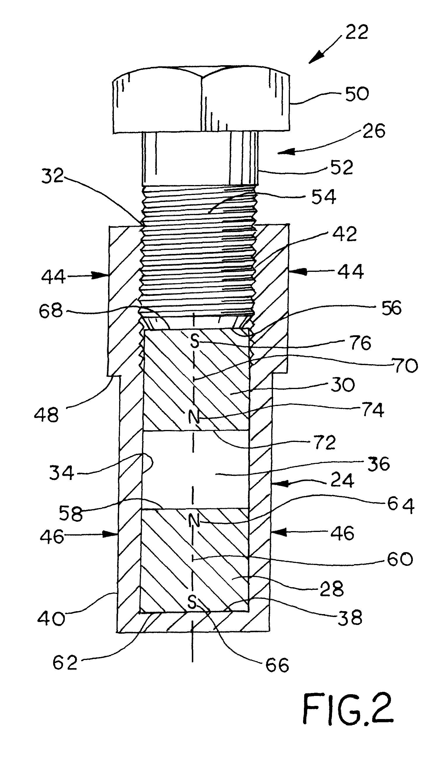
[0025]As illustrated in FIG. 2, an adjustable magnetic target 22 includes a body tube 24 and an adjusting member 26 that is longitudinally received into the body tube 24. A stationary axially-magnetized SmCo magnet 28 is disposed within the body tube 24, and a movable axially-magnetized SmCo magnet 30 is also disposed within the body tube 24 between the adjusting member 26 and the stationary SmCo magnet 28. The movable SmCo magnet 30 engages the adjusting member 26 such that when the adjusting member 26 is displaced either towards or away from the stationary SmCo magnet 28, the movable SmCo magnet 30 is also displaced towards or away from the stationary SmCo magnet.

[0026]FIG. 2 shows a cross-sectional view of the body tube 24. The body tube 24 preferably has a generally cylindrical shape having a circular cross-section. However, the body tube 24 may have any cross-sectional shape, such as a polygon or an oval, for example. The body tube 24 may be formed from metal or plastic, and ma...


PUM


Abstract

A magnetic target is provided for use with a magnetic proximity switch. The magnetic target includes a cylindrical body tube having an open end that partially defines a bore. A stationary magnet is located within the bore opposite the open end, and a movable magnet is disposed within the bore between the stationary magnet and the open end. An adjusting member is received into the bore, and a contact surface of the adjusting member engages the movable magnet. When the adjusting member is axially displaced, the contact surface causes a corresponding displacement of the movable magnet relative to the stationary magnet, eventually causing the magnetic flux field of each magnet to expand in a radial direction away from the longitudinal axis of each magnet. The stationary magnet and the movable magnet may be either axially-magnetized samarium-cobalt magnets or axially-magnetized neodymium magnets.

Description

FIELD OF THE DISCLOSURE[0001]This disclosure relates generally to magnetic proximity switches, and, more particularly, to a magnetic target that is detected by a sensor of a magnetic proximity switch.BACKGROUND[0002]Magnetic proximity switches, also known as limit switches, are commonly used for linear position sensing. Typically, magnetic proximity switches include a target and a sensor, the sensor being coupled to a switching circuit having two leaf portions, a stationary portion and a movable portion hermetically sealed within a glass enclosure that is itself contained within a switch body. When the target, which generally includes a permanent magnet contained within a housing, passes within a predetermined range of the sensor, the magnetic flux generated by the target magnet causes the movable leaf to contact the stationary leaf, thereby closing the switch.[0003]The ability of the sensor to detect the position of the magnetic target without the need for physical contact allows t...

Claims


Application Information

Patent Timeline
Patent Type & Authority Patents(United States)
IPC IPC(8): H01H7/02H01H9/00
CPCH01F7/0284H01H36/0013H01F7/0289
Inventor LAFOUNTAIN, ROBERT L.BI, XUEGUANGSIMMONS, MICHAEL
Owner GENERAL EQUIP & MFG COMPANY INC D B A TOPWORX
Why Eureka
Try Eureka