Heat generation control device for heat-assisted magnetic recording and reproducing apparatus

a technology of heat generation and control device, which is applied in the direction of digital signal error detection/correction, instruments, recording signal processing, etc., can solve problems such as wrong erasur

Inactive Publication Date: 2012-09-11
SHARP KK
View PDF23 Cites 7 Cited by
  • Summary
  • Abstract
  • Description
  • Claims
  • Application Information

AI Technical Summary

Benefits of technology

[0015]The present invention is attained in view of the conventional problem. An object of the present invention is to provide a heat generation amount control device that easily makes it possible to appropriately carry out at least either recording / reproduction with respect to a magnetic recording medium, a program and a recording medium for the heat generation amount control device, a magnetic disk device, and a heat generation amount control method.
[0017]According to the invention, the first computing means controls the heat generation amount of the heat generation means according to the heat generation amount control information that is arranged in advance to correspond to information on a temperature that is obtained from the temperature detection means. Therefore, if the predetermined heat generation amount is a heat generation amount with which the magnetic recording medium is appropriately heated, it becomes possible to set the heat generation amount control information in accordance with the temperature variation even in a case where the heat generation amount control information varies which heat generation amount control information is for controlling the heat generation means heating the recording area or the reproduction area of the heat recording medium in accordance with the temperature variation. Because an instruction on the heat generation amount that is obtained by the heat generation means is given according to the heat generation amount control information in accordance with the temperature variation, it becomes possible to prevent wrong erasing of the information that has been recorded. This wrong erasing occurs due to excessive temperature increase in the recording area or the reproduction area of the magnetic recording medium. In other words, it becomes possible to appropriately carry out at least either recording or reproduction with respect to the magnetic recording medium. Furthermore, because recording or reproduction can be appropriately carried out with respect to the magnetic recording medium as described above, it becomes unnecessary to take time for examining, by performing test writing or test reading, heat generation amount control information appropriate for carrying out recording or reproduction with respect to the magnetic recording medium.
[0018]Further, even in a case where the test writing or the test reading is performed, the test writing or the test reading can be performed based on the appropriate heat generation amount control information and the heat generation amount control information that is determined by the first computing means. Accordingly, the number of trying the test writing or the test reading can be reduced. As a result, it becomes possible to shorten a time for determining the heat generation amount control information of the heat generation means.
[0019]This easily makes it possible to appropriately carry out at least either recording or reproduction with respect to the magnetic recording medium, in accordance with the temperature variation.
[0021]The present invention easily makes it possible to appropriately carry out at least either recording or reproduction with respect to the magnetic recording medium, in accordance with temperature variation.

Problems solved by technology

This wrong erasing occurs due to excessive temperature increase in the recording area or the reproduction area of the magnetic recording medium.

Method used


Image

  • Heat generation control device for heat-assisted magnetic recording and reproducing apparatus
  • Heat generation control device for heat-assisted magnetic recording and reproducing apparatus
  • Heat generation control device for heat-assisted magnetic recording and reproducing apparatus

Examples


embodiment 1

[0037][Embodiment 1]

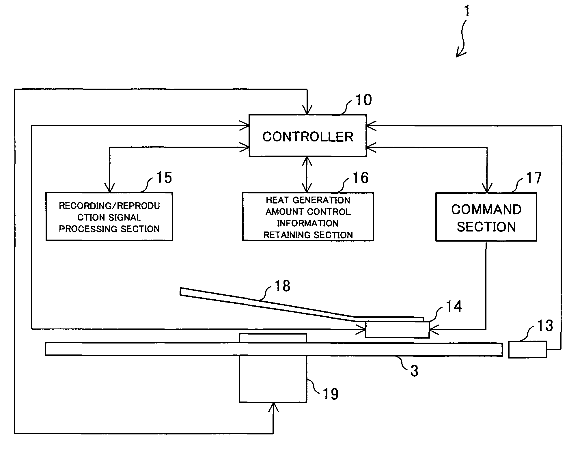
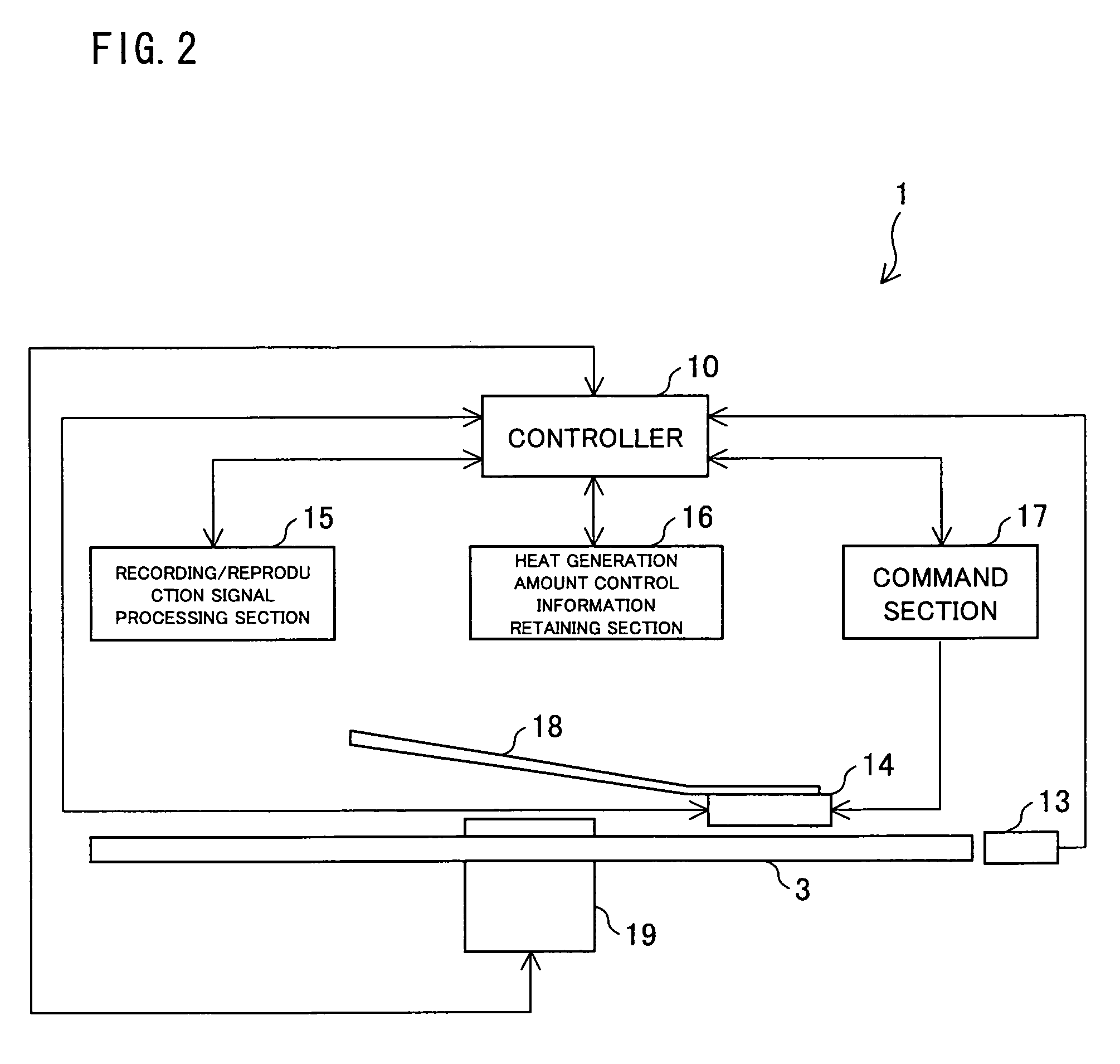
[0038]The following explains one embodiment of the present invention, with reference to FIGS. 1 through 8. First, an arrangement of a magnetic recording / reproducing device (magnetic disk device) 1 is schematically explained with reference to FIG. 2. FIG. 2 is a block diagram illustrating an arrangement of the magnetic recording / reproducing device 1 according to the present embodiment.

[0039]As illustrated in FIG. 2, the magnetic recording / reproducing device 1 of the present embodiment includes a controller 10, a temperature sensor (temperature detection means) 13, a recording / reproducing head 14, a recording / reproduction signal processing section 15, a heat generation amount control information retaining section (heat generation amount control information retention means) 16, a command section (command means) 17, a suspension 18, and a spindle motor (spin means) 19. Moreover, a magnetic recording medium 3 is placed so as to be fixed to the spindle motor 19. Note t...

embodiment 2

[0081][Embodiment 2]

[0082]The following explains another embodiment of the present invention, with reference to FIGS. 9 and 10. An arrangement other than an arrangement explained in the present embodiment is the same as an arrangement in the Embodiment 1. For convenience of an explanation, members given the same reference numerals as the members explained in the Embodiment 1 respectively have identical functions and the explanations thereof are omitted. A heat generation amount control device 12 of the present embodiment is different from that in the arrangement of the Embodiment 1 in that the heat generation amount control device 12 of the present embodiment includes a second computing section 52 that carries out test wiring and / or test reading.

[0083]First, the test wiring is explained. Test writing, in general, is to determine an optimum recording condition for carrying out recording with respect to the recording medium. In the test writing, for the purpose of optimizing a conditi...

embodiment 3

[0109][Embodiment 3]

[0110]The following explains another embodiment of the present invention, with reference to FIGS. 11 and 12. An arrangement other than an arrangement explained in the present embodiment is the same as an arrangement in the Embodiment 2. For convenience of an explanation, members given the same reference numerals as the members explained in the Embodiments 1 and 2 respectively have identical functions and the explanations thereof are omitted. A heat generation amount control device 12 of the present embodiment is different from the arrangement of the Embodiment 2 in that the heat generation amount control device 12 of the present embodiment includes a correcting section 63.

[0111]First, an arrangement of the heat generation amount control device 12 of the present embodiment is explained with reference to FIG. 11. FIG. 11 is a functional block diagram of the heat generation amount control device 12 of the present embodiment.

[0112]As illustrated in FIG. 11, the heat ...


PUM

PropertyMeasurementUnit
temperatureaaaaaaaaaa
threshold currentaaaaaaaaaa

Abstract

According to the present invention, heat generation amount control information for controlling a heat generation amount of a heat generating section (20) is arranged to correspond to each of temperatures so that a predetermined heat generation amount is obtained at each of the temperatures. The present invention includes a first computing section (41) that controls the heat generation amount of the heat generating section (20) according to the heat generation amount control information that is arranged in advance to correspond to temperature information that is obtained from a temperature sensor (13). This easily makes it possible to appropriately carry out at least either recording or reproduction with respect to a magnetic recording medium.

Description

TECHNICAL FIELD[0001]The present invention relates to a heat generation amount control device that is used at least either for heating a recording area for recording magnetic information by use of a recording head or for heating a reproduction area for reproduction of information by use of a reproducing head that has a magneto resistive effect, a program and a recording medium for the heat generation amount control device, a magnetic disk device, and a heat generation amount control method.BACKGROUND ART[0002]Recently, a technique for realizing a high-density recording has been developed as a result of fusion of optical technology and magnetic recording / reproducing technology. For example, Patent Document 1 discloses a magnetic recording medium made of a ferromagnetic substance whose compensation temperature is substantially a room temperature, and a heat-assisted magnetic recording / reproducing method in which recording / reproduction of information is carried out, by using a laser be...

Claims


Application Information

Patent Timeline
Patent Type & Authority Patents(United States)
IPC IPC(8): G11B11/00
CPCG11B5/09G11B2005/0021
Inventor NAKANO, IKUOMURAKAMI, YOSHITERU
Owner SHARP KK
Why Eureka
Try Eureka