Sieve, sifting device, solder balls, and method of sifting spherical particles

a spherical particle and sifting device technology, applied in the direction of solid separation, cleaning process and apparatus, cleaning using liquids, etc., can solve the problems of ineffective sifting of particles, constant oscillation, and clogging of holes, so as to increase the classification rate, the operation rate of the sieve may be enhanced, and the effect of increasing the classification ra

Inactive Publication Date: 2012-09-18
OPTNICS PRECISION
View PDF11 Cites 6 Cited by
  • Summary
  • Abstract
  • Description
  • Claims
  • Application Information

AI Technical Summary

Benefits of technology

[0032]That is, the present invention may enhance sieve efficiency and greatly improve the productivity of sifting operations by constituting a meshed sieve of metal, applying ingenuity to the shapes of the holes, improving the arrangement of the holes, and arranging lines of the holes in accordance with oscillation movements.
[0034]In the present invention, a plate-form sieve in a sifting device is fabricated of metal, the shapes of holes that sift spherical particles are formed as long holes, and the long holes are plurally provided such that a line extending in the length direction of a long hole is made orthogonal to a length direction of others of the long holes. Thus, when particles are being classified, even if the sieve is oscillated in a number of oscillation directions, it is easy for the particles to pass through the long holes, and the classification rate is increased. Therefore, an operation rate of the sieve may be enhanced. In particular, the classification rate is further increased when the long holes are plurally provided such that the lines extending in the length directions are orthogonal to the length directions of others of the long holes.
[0035]Moreover, the operational efficiency of the sieve may be made particularly effective by making widths of the long holes equal to the diameter of the particles to be classified or at least the diameter of the particles to be classified, making the lines extending in the length direction of the long holes orthogonal to length direction midpoints of others of the long holes, and forming corner portions of the long holes of the sieve with filleting. In particular, by forming corner portions of the long holes of the sieve to have roundness, an additional effect may be provided in that cracking or the like that is caused by the sieve being subjected to mechanical oscillations and mechanically fatigued and that damages the sieve may be prevented.
[0036]The sieve is fabricated by electroforming. Specifically, using nickel or a nickel alloy, fluorocarbon particles of 0.1 μm to 2 μm are composite-electrodeposited with nickel plating at the surface of the sieve, and fluorocarbon particles are additionally composite-electrodeposited with nickel plating up to a thickness of 1 μm to 30 μm from both the length direction hole walls of each long hole in the sieve. Therefore, by controlling and carrying out a series of operations to fabricate, for example, a 10 μm thick sieve from an electrocast base plate by composite electrodeposition of 0.1 μm to 2 μm fluorocarbon particles with nickel plating, then peeling a nickel mesh from the surface of the electrocast base plate, and then additionally performing composite electrodeposition of fluorocarbon particles with nickel plating up to a thickness of 1 μm to 30 μm from the two length direction hole walls of each long hole in the sieve, the size of the long holes may be controlled while the thickness of the sieve is assured. Thus, the thickness of the sieve mesh may be thoroughly assured in relation to a proportional area of the long holes. Furthermore, because the fluorocarbon particles are additionally composite-electrodeposited with the nickel plating up to a thickness from 1 μm to 30 μm at the two length direction hole walls of each long hole in the sieve, cross-sectional shapes of the long holes have narrow depth direction central portions. Consequently, durations of contact with the insides of the hole walls when the particles to be classified are passing through the long holes are minimized, pass-through durations may be minimized, and the operational efficiency of the sieve may be made even more effective. The composite electrodeposition of the fluorocarbon particles in the nickel plating has effects of improving smoothness of the surfaces of the sieve, and of enhancing abrasion resistance and greatly extending the lifetime of the sieve.
[0037]In addition, because the sieve is oscillated by the oscillation unit, the particles may slip through the holes and fall down as quickly as is possible after the particles come into contact with the holes of the sieve, and the operational efficiency of the sieve may be made still more effective.

Problems solved by technology

When such a sieve mesh is used, the sieve is driven during a sifting operation in a vertical direction or a lateral direction, or alternatively radial directions or the like, and is constantly subjected to oscillations.
However, with vertical oscillations, the particles jump about at the edges of the sieve holes, and may not pass through the holes as hoped.
Further, with oscillations to front, rear, left and right, referred to as two-dimensional horizontal oscillations, depending on the speeds and acceleration thereof, there are many opportunities for the particles to pass upward from the holes and therefore the particles may not be efficiently sifted.
Further still, when the shapes of the sieve holes are close to the related art squares or perfect circles, that is, when the holes are circumscribed by shortest arcs, the particles stick so as to fill the cavities, and the holes become clogged.
Therefore, in a common related art sieve mesh, it is uncertain that there are sufficient chances for particles moving in accordance with lateral direction forces in the plane of the mesh to pass through the holes, and sifting operations are not efficient.
However, a phenomenon then occurs of particles that are temporarily caught in the holes being difficult to remove from the holes, because of the force of the negative pressure, and suchlike.
Thus, holes in related art sieve meshes are prone to clogging, and this is not efficient.
However, there is still no definitive means for making sifting operations more efficient.

Method used


Image

  • Sieve, sifting device, solder balls, and method of sifting spherical particles
  • Sieve, sifting device, solder balls, and method of sifting spherical particles
  • Sieve, sifting device, solder balls, and method of sifting spherical particles

Examples


first exemplary embodiment

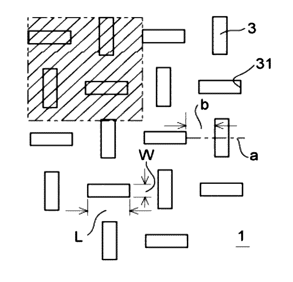
[0070]As illustrated in FIG. 1, a plate-form sieve 1 of a sifting device relating to the present invention (the first exemplary embodiment) is fabricated of a metal, for example, nickel or a nickel alloy, and has long holes 3 with hole shapes that sift, for example, solder balls 2 illustrated in FIG. 6. The long holes 3 are plurally provided in the sieve 1 such that lines extending in the length directions thereof cross length direction midpoints a of others of the long holes 3. A spacing b of the long holes 3 is set to 3 times to 5 times a diameter x of the solder balls 2 to be classified, for example, 3 times, and length direction lengths L of the long holes 3 are set to 3 times the diameter x of the solder balls 2 to be classified. Further, a width W of the long holes 3 is set to equal the diameter x of the solder balls 2 to be classified

[0071]The diameter x of the solder balls 2 to be classified in the first exemplary embodiment is 67 μm. A thickness T1 of the sieve 1 is 35 μm.

[...

second exemplary embodiment

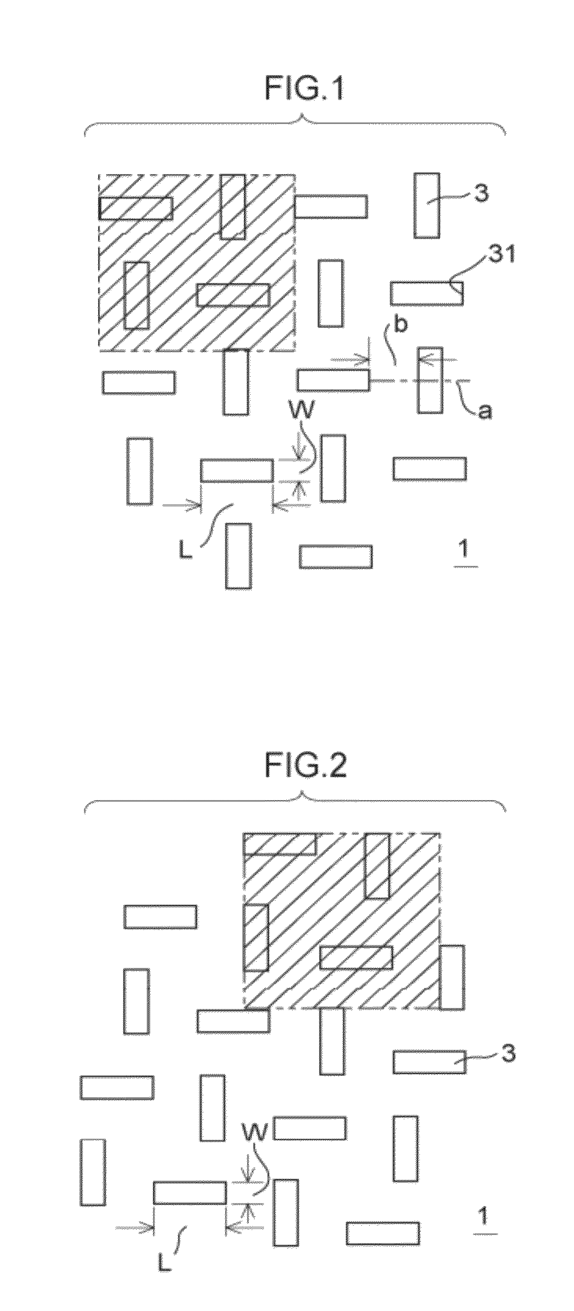
[0075]As illustrated in FIG. 2, the sieve 1 of a sifting device of the second exemplary embodiment has a structure that differs from the first exemplary embodiment in that the long holes 3 that are plurally provided in the sieve 1 are formed such that the lines extending in the length directions thereof are orthogonal to arbitrary positions in the length directions of others of the long holes 3.

[0076]Now, a method of fabricating the sieve 1 of the above-described first exemplary embodiment or second exemplary embodiment using electroforming is described on the basis of FIG. 6.

[0077]In the electroforming described below, generally, bringing holes closer to other holes is sufficient as a method for raising a hole opening ratio. In practice however, a result of neighboring holes being made denser and dividing walls therebetween becoming thinner is that strength of the sieve 1 falls and cannot withstand usage. Accordingly, if adjoining walls (the hole walls 31 of the long holes 3) are m...


PUM


Abstract

This invention aims to enhance efficiency of a sieve and to greatly improve productivity of a sifting operation. There is provided a sieve comprising a metal plate including long holes, wherein the long holes are plurally provided such that lines extending in length directions thereof cross one another.

Description

CROSS-REFERENCE TO RELATED APPLICATION[0001]This application is based on and claims priority under 35 USC 119 from Japanese Patent Application No. 2009-206057 filed on Sep. 7, 2009 and Japanese Patent Application No. 2009-217027 filed on Sep. 18, 2009, the disclosures of which are incorporated by reference herein.BACKGROUND[0002]1. Technical Field[0003]The present invention relates to a sifting device provided with a sieve made of metal that has excellent classification efficiency, specifically proposes an arrangement of plural holes provided in the sieve, and relates to a sifting device that may enhance efficiency of the sieve and may greatly improve productivity of sifting operations.[0004]2. Related Art[0005]Operation rates of sieves in sifting devices that efficiently sift spherical particles are known to be an important technological factor directly affecting overall industrial productivity. In particular, efficiently sifting spherical particles that are close to perfectly circ...

Claims


Application Information

Patent Timeline
Patent Type & Authority Patents(United States)
IPC IPC(8): B07B1/46
CPCB07B1/4618B07B1/469B08B3/026B08B2203/007B08B2230/01
Inventor KINUTA, SEICHIN
Owner OPTNICS PRECISION
Why Eureka
Try Eureka