Modular compact adsorption bed

a compact, adsorbent bed technology, applied in the direction of dispersed particle separation, separation process, chemical apparatus and processes, etc., can solve the problems of significantly reducing plant throughput and difficult to reduce the size of the adsorbent bed structure, and achieves significant capital cost savings, easy loading of adsorbent materials, and increased bed frontal area.

Active Publication Date: 2012-09-18
PRAXAIR TECH INC
View PDF16 Cites 64 Cited by
  • Summary
  • Abstract
  • Description
  • Claims
  • Application Information

AI Technical Summary

Benefits of technology

[0014]The present invention provides a novel modular compact design for adsorbent bed structures used in adsorption-based gas separation processes and is particularly suitable for cyclic processes such as pressure swing adsorption (PSA), vacuum swing adsorption (VSA) and vacuum pressure swing adsorption (VPSA) processes. The modular compact design consists of individual module adsorbent bed units which can be connected, stacked or otherwise coupled to form adsorbent bed structures of varying sizes and shapes. As mentioned above, significant capital cost savings can be achieved using the modular and compact adsorbent bed units in adsorption-based gas separation plants. The modular compact design results in smaller modular adsorbent bed units that enable easier adsorbent material loading compared to bulky conventional adsorbent beds. The modular compact design also facilitates increased bed frontal areas and shorter bed depths as desired.
[0015]According to this invention, a conventional packed adsorbent bed used in a gas separation plant is replaced with a modular compact adsorbent bed structure containing a plurality of modular adsorbent bed units. These modular adsorbent bed units provide higher capacity of gas product per unit volume of adsorbent material (i.e., increased adsorbent utilization) as compared to that obtained from a conventional packed adsorbent bed. They also provide substantially reduced pressure drop through the adsorbent bed structure through the use of shorter bed depths and optionally increased flow area.

Problems solved by technology

However, it is generally difficult to reduce the size of adsorbent bed structures without also significantly reducing the plant throughput.
Modifications in the bed geometry and process parameters bring additional challenges, such as in proper design of bed or vessel shapes, proper distribution of gas flow, management of void volumes, adsorbent loading and containment constraints, and operation of the plant components at faster rates.

Method used


Image

  • Modular compact adsorption bed
  • Modular compact adsorption bed
  • Modular compact adsorption bed

Examples


example

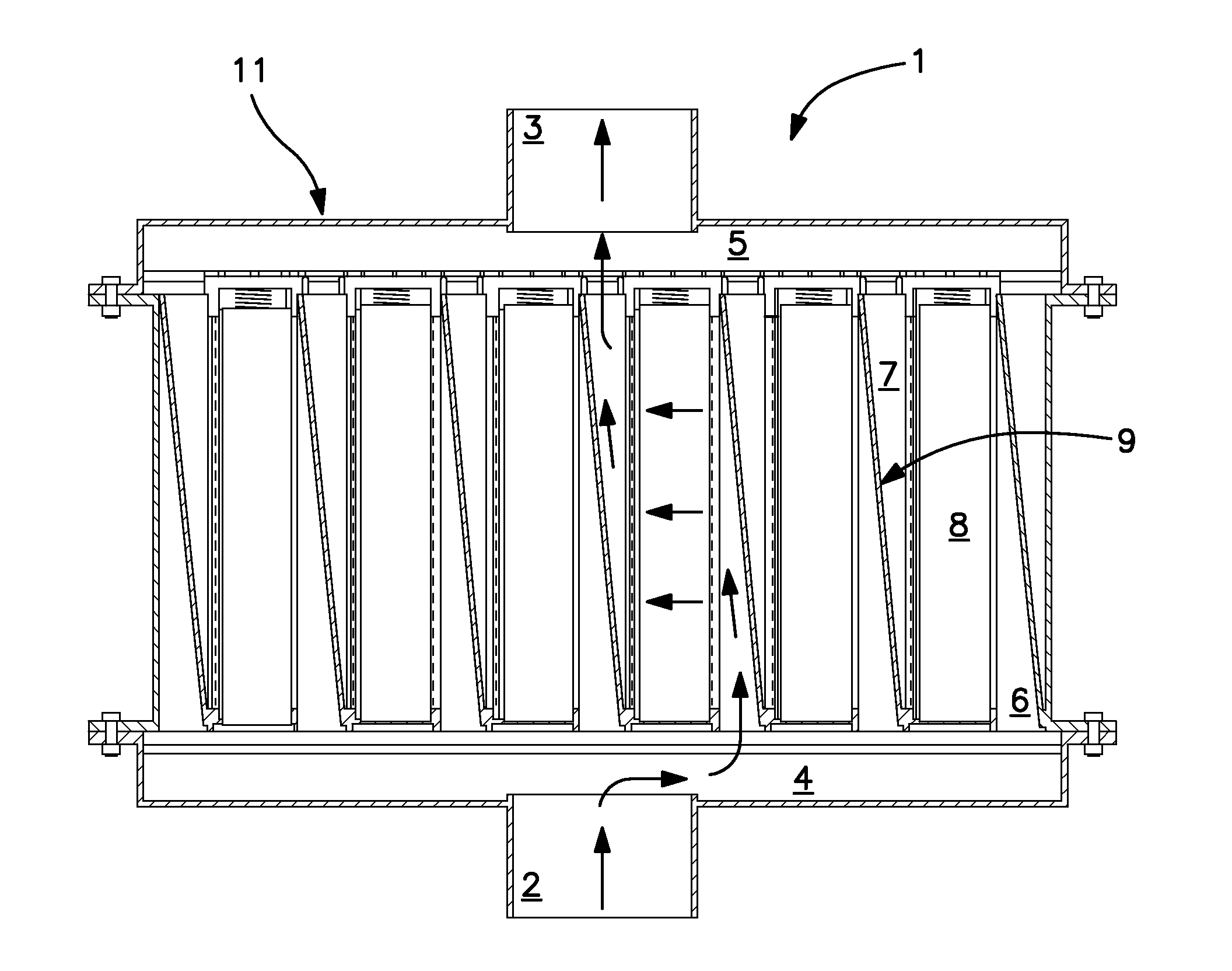
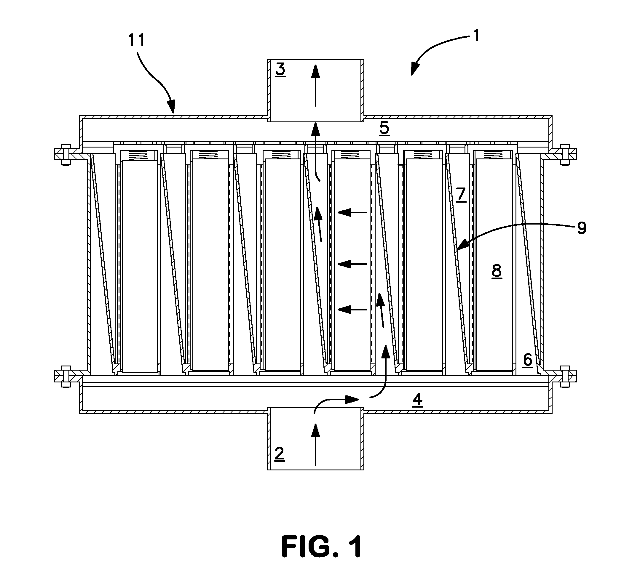
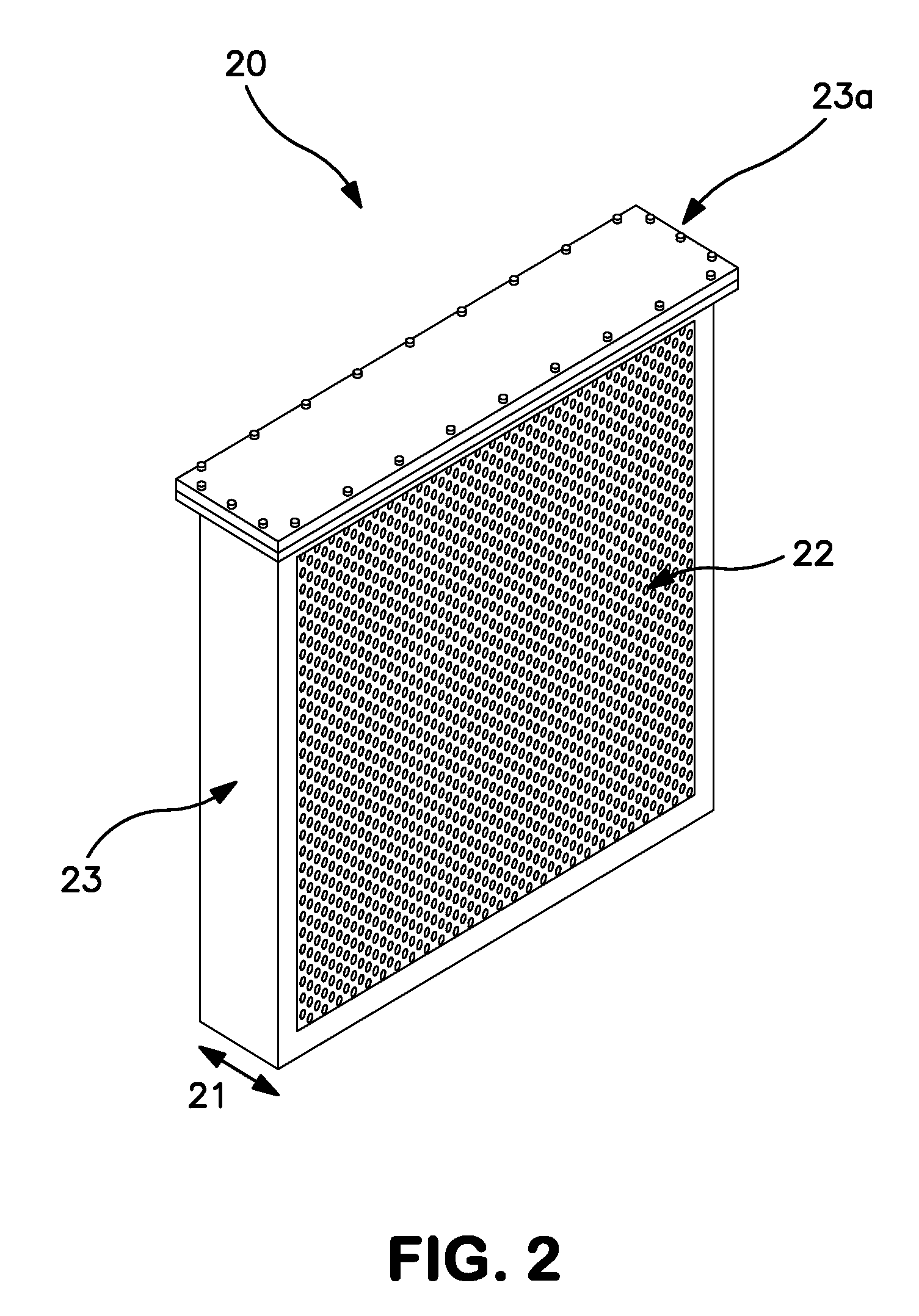
[0064]An adsorption bed structure containing a plurality of modular adsorbent beds units as shown in FIG. 1 was designed and compared to a conventional bed capable of producing the same amount of gas product. Each of the modular adsorbent bed units (8) were designed as flat rectangular boxes 1.0 m×1.0 m (3.5 ft×3.5 ft) square frontal bed area and 0.2 m (8.0 in) bed length as shown in FIG. 2. The volume within each unit was filled with adsorbent material, and gas flow entered into and exited out of this adsorbent material through the opposing two largest faces. There is no gas flow into or out of this unit through the other four surfaces. Feed and product channels (6, 7) on both sides of the adsorbent material were symmetric and tapered in shape, with a 5° taper angle. Each feed and product channel was wider near the entrance or exit end and thinner at the closed end.

[0065]There are six modular adsorbent bed units, as shown in FIG. 1, with identical dimensions to provide the desired ...


PUM


Abstract

A modular and compact adsorbent bed structure is disclosed for use in an adsorption-based gas separation plant. The conventional adsorbent bed in a gas separation plant is replaced with a plurality of modular adsorbent bed units connected to make the adsorbent bed structure. Modular adsorbent bed units of this invention provide higher capacity of product per unit volume of adsorbent material (i.e., increased adsorbent utilization) as compared to that obtained from conventional adsorbent beds. The modular design requires lower fabrication costs; is easier to transport; has less maintenance and repair requirements; and is easier to load with adsorbent material.

Description

FIELD OF THE INVENTION[0001]The present invention relates generally to the field of adsorption beds, particularly adsorption beds for use in gas separation processes. More specifically, this invention relates to modular compact adsorbent bed units which can be combined to provide full sized adsorbent bed structures used in adsorption-based gas separation processes.BACKGROUND OF THE INVENTION[0002]Gas separation processes using adsorbent beds are well known in the art. Typical adsorption-based processes include those where a gas component within a multi-component feed gas is selectively adsorbed. Of particular interest are cyclic processes wherein the adsorbed gas is removed from the adsorbent material in a reversing gas flow such as pressure swing adsorption (PSA), vacuum swing adsorption (VSA) and vacuum pressure swing adsorption (VPSA) processes. These processes have evolved significantly over the last few years with improvements being made to the adsorbent materials, the adsorben...

Claims


Application Information

Patent Timeline
Patent Type & Authority Patents(United States)
IPC IPC(8): B01D53/02
CPCB01D53/0407
Inventor CELIK, CEM E.ACKLEY, MARK WILLIAMSMOLAREK, JAMES
Owner PRAXAIR TECH INC
Why Eureka
Try Eureka