Method of manufacturing an ink jet print head

a printing head and ink jet technology, applied in the field of ink jet printing head construction, can solve the problems of complex three-dimensional geometry, failure to have an ideal smooth surface, and difficulty in achieving the required degree of high levelness, and achieve the effect of short tim

Inactive Publication Date: 2012-09-25
CANON KK
View PDF11 Cites 31 Cited by
  • Summary
  • Abstract
  • Description
  • Claims
  • Application Information

AI Technical Summary

Benefits of technology

[0017]The present invention has been accomplished to solve the aforementioned problems. It is therefore an object of this invention to provide a method of manufacturing an ink jet print head that allows the printing element substrate to be bonded to a support surface accurately in a short time.

Problems solved by technology

The supporting member 120, however, is generally a molded product for reduced cost and improved processability, so that its support surface 121 may often result in a complex three-dimensional geometry, failing to have an ideal smooth surface.
The height variations make it difficult to achieve the degree of high levelness required in recent years.
However, increasing the thickness of the adhesive layer naturally increases the amount of heat required to harden the thermosetting adhesive to a sufficient degree of hardness, i.e., the time it takes for the adhesive to harden.
This in turn increases cost and time in the mass production of the ink jet print heads.

Method used


Image

  • Method of manufacturing an ink jet print head
  • Method of manufacturing an ink jet print head
  • Method of manufacturing an ink jet print head

Examples


embodiment 1

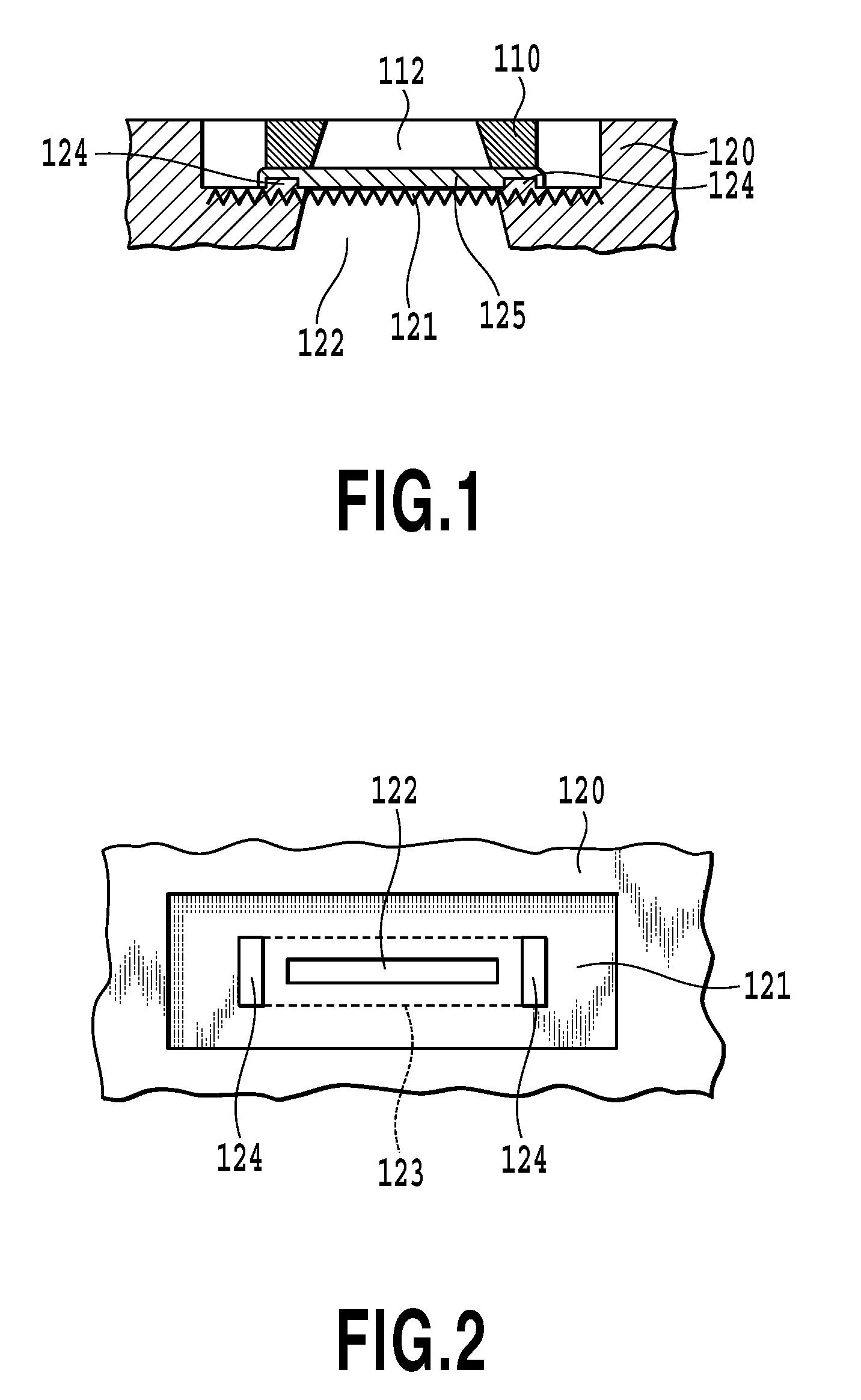
[0035]FIG. 1 is a cross-sectional view showing a printing element substrate 110 bonded to a supporting member 120 in the ink jet print head of this embodiment. FIG. 2 is a top view showing an outline of a support surface 121 of the supporting member 120 before bonding. The support surface 121 on which to support the printing element substrate 110 is a molded product that has an ink supply path 122 at the central part thereof. Setting the printing element substrate 110 accurately at a connecting position 123 marked with a broken line allows an ink supply port 112 of the printing element substrate 110 to be connected to the ink supply path 122, securing a stable supply of ink to the printing element substrate 110. In this embodiment, at both ends of the elongate connecting position 123 there are two raised flat portions 124. The provision of the raised flat portions 124 can reduce the thickness of a thermosetting adhesive 125 between the printing element substrate 110 and the support ...

embodiment 2

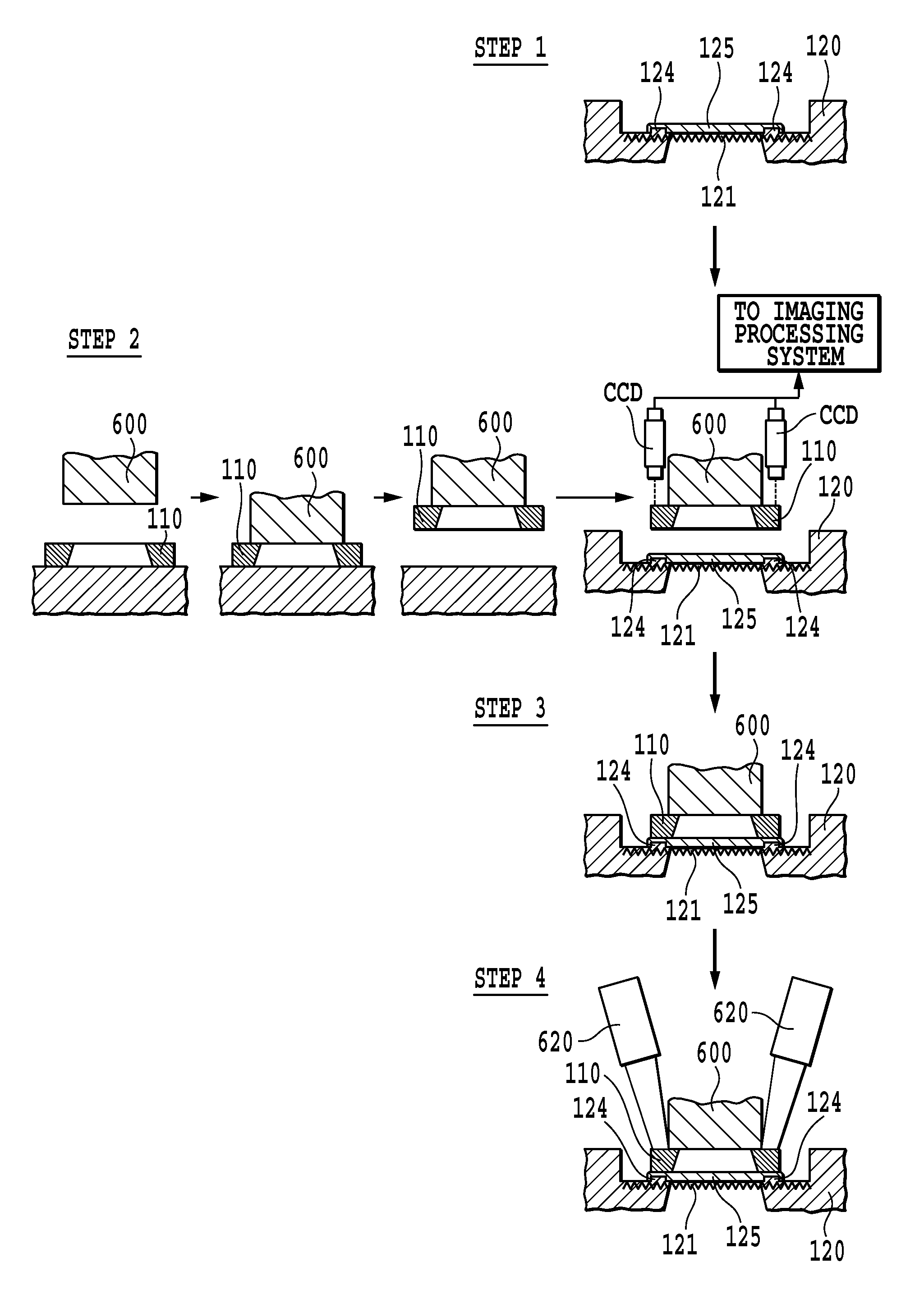
[0048]FIG. 6 is a cross-sectional view showing the printing element substrate 110 bonded to the supporting member 120 in the ink jet print head of this embodiment. FIG. 7 is a top view showing an outline of the support surface 121 of the supporting member 120 before bonding. In this embodiment, two raised flat portions 126 are formed at a central part of the connecting position 123. The provision of the raised flat portion at this position allows the thermosetting adhesive 125 between the printing element substrate 110 and the support surface 121 to be partly reduced.

[0049]FIG. 8 shows how the printing element substrate 110 is bonded and fixed to the support surface 121 having the raised flat portions 126 in a print head assembly process of this embodiment.

[0050]First, in step 1, the support surface 121 of the supporting member 120 is applied with a thermosetting adhesive 125. The thermosetting adhesive used here preferably has a high viscosity, as in embodiment 1, so that it does n...


PUM

PropertyMeasurementUnit
thickaaaaaaaaaa
heightaaaaaaaaaa
heightaaaaaaaaaa

Abstract

A method of manufacturing an ink jet print head capable of bonding the printing element substrate to the support surface with high precision in a reduced period of time is provided. For this purpose, raised flat portions are formed in the support surface of the supporting member to provide in an adhesive layer between the printing element substrate and the supporting member a portion of the thermosetting adhesive that is thinner than others. After the relative positions of the printing element substrate and the supporting member are adjusted, the thin portions of the adhesive layer are hardened. This enables the printing element substrate to be bonded to the supporting member in a relatively short period of time. As a result, if there are undulations on the support surface, the printing element substrate can be bonded to the supporting member with high precision, improving the mass productivity of the print head.

Description

BACKGROUND OF THE INVENTION[0001]1. Field of the Invention[0002]The present invention relates to a construction of an ink jet print head that can be installed in an ink jet printing apparatus and also to a method of manufacturing the same. More specifically, the invention relates to a method of bonding together with high precision in a short period of time a printing element substrate formed with ink ejecting print elements and a supporting member for supporting the printing element substrate and supplying it with ink.[0003]2. Description of the Related Art[0004]The ink jet printing apparatus uses a print head having a plurality of printing elements that eject ink according to print data to form dots and therefore an image on a print medium. In recent years, great efforts are being made to develop a print head capable of ejecting smaller ink droplets at high density to print highly defined images with enhanced precision.[0005]FIG. 9 is an exploded perspective view of a side shooter ...

Claims


Application Information

Patent Timeline
Patent Type & Authority Patents(United States)
IPC IPC(8): B21D53/76H05B3/03
CPCB41J2/1623B29C65/1406Y10T29/49083B29C65/5057B29C66/9672B29C2035/0827B29K2083/00B29L2031/767B41J2002/14362B41J2202/22B29C65/1412Y10T156/10B29C66/53461B29C65/4835Y10T29/49133Y10T29/49401B29C65/00
Inventor MIYAZAKI, HIROTAKA
Owner CANON KK
Why Eureka
Try Eureka