LED driver circuit with over-current protection during a short circuit condition

a technology of short circuit and over-current protection, which is applied in the direction of process and machine control, lighting and heating apparatus, instruments, etc., can solve the problems of large heating value, local over-heating, and corresponding sharp temperature ris

Inactive Publication Date: 2012-09-25
PANASONIC CORP
View PDF3 Cites 23 Cited by
  • Summary
  • Abstract
  • Description
  • Claims
  • Application Information

AI Technical Summary

Benefits of technology

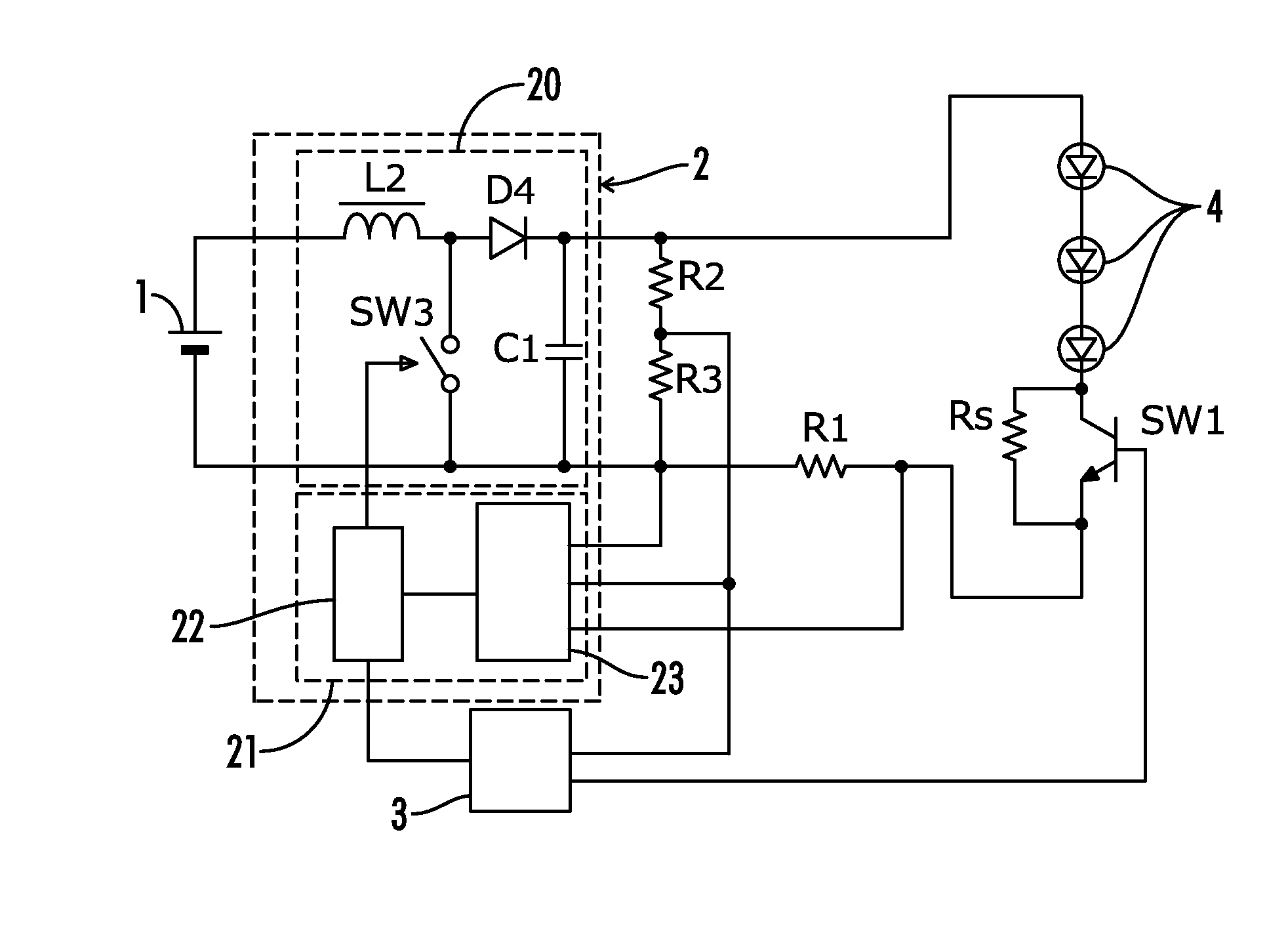
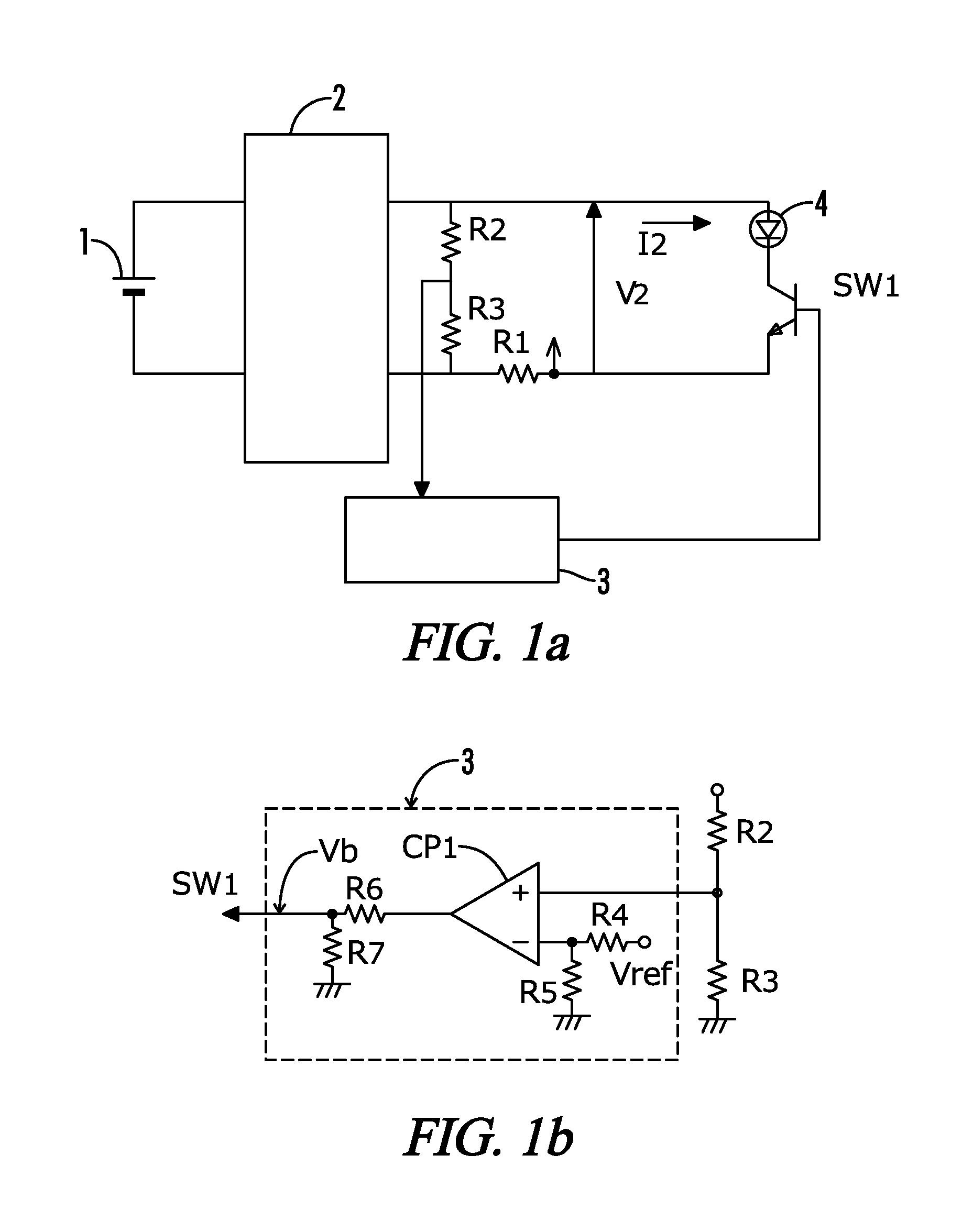
[0023]According to this aspect, if a voltage detected by the voltage sensor is equal to or less than a predetermined value defined for short circuit determination for the LED, the short circuit response circuit determines that the LED is short-circuited and acts to restrict a current supplied to the LED, whereby an over-current is not continuously provided into the LED. The driver circuit is therefore capable of preventing further damage to the LED associated with a temperature rise occurring when the LED has a short circuit failure.
[0025]According to this aspect, a simplified configuration can be achieved because the switching element in the converter for use in lighting the LED can further be used to perform the functions of the above LED current restriction circuit. The LED current restriction circuit can further be incorporated in the current control circuit, allowing miniaturization of the LED driver circuit.
[0027]According to this aspect, a current flowing into the LED is restricted by the switching element connected in series with the LED, so that a period of time for an over-current to flow into the LED in a short circuit state thereof can be minimized by a relatively simple configuration.
[0029]According to this aspect, if a voltage is equal to or less than the predetermined value in this specific range, the short circuit response circuit spuriously determines the LED is short-circuited. It should be noted in particular that a voltage lower than ⅓ times a normal voltage across the LED will result in a longer period of time for an over-current to flow into the short-circuited LED, whereas a voltage higher than 5 / 9 times a normal voltage will result in larger variations of a voltage across of the LED due to deterioration of the LED with the elapse of time and manufacturing variations among LEDs, wherein malfunction of the short circuit response circuit may be possibly observed. However, these problems can be effectively prevented.
[0033]According to this aspect, a current supplied to the LED can be restricted by using both the switching element connected in series with the LED and the switching element arranged in the current control circuit, thereby making it possible to prevent the LED from being damaged while protecting the driver circuit when the LED is short-circuited.
[0035]According to this aspect, even if the LED is short-circuited, a restricted current can be continuously made to flow while preventing the LED from being damaged. Particularly when an array of LEDs are connected in series, proper lighting of LEDs which are not short-circuited can be maintained while simultaneously preventing short-circuited LEDs from being damaged. Therefore, extinguishing the entire LED array can be avoided even where the LED array is partially short-circuited.

Problems solved by technology

Therefore, a short circuit occurring in the high output LED 4 will result in a large heating value with a corresponding sharp temperature rise, followed by not only extinguishing of the LED 4 but other problems.
A short circuit of the LED chip causes local overheating due to current concentration or other reasons, and the heat causes thermal expansion of air included in the LED 4 and / or sharp thermal expansion by evaporation of water included in a resin which may be used for an adhesive, cover or like purposes, whereby the LED 4 may be possibly damaged.
In such cases, a short circuit of the LED 4 is accompanied by the failing of one or more components which constitute the LED 4 (such as an LED chip, adhesive, a substrate and a cover) on a lamp and fixture of a illumination device, internally contaminating and / or damaging the lamp and fixture, and possibly hindering the reuse of the illumination device.
Particularly because the high output LED 4 often uses solder in place of a metal wire as an electrical connection material, the LED 4 tends to be damaged by a short circuit rather than an open circuit resulting from disconnection of a metal wire.
Moreover, a short circuit of the LED 4 not only causes a complete short circuit but also complicates a magnitude of a decrease of the forward direction voltage Vf.
As a result, a short circuit of the LED 4 is accompanied by a longer period of time for an over-current to flow into the LED 4 with an increased heating value of the LED 4, whereby damage to the LED 4 may result and possibly cause a large scale contamination, impairment, or other such problems in a lighting fixture.
However, this is based on the assumption that current is stopped after the LED 4 is short-circuited with a temperature rise in an LED chip or other components, which means protection of the driver circuit can be achieved without sufficiently preventing contamination and impairment in the lamp and fixture or other components due to the LED 4 being damaged.
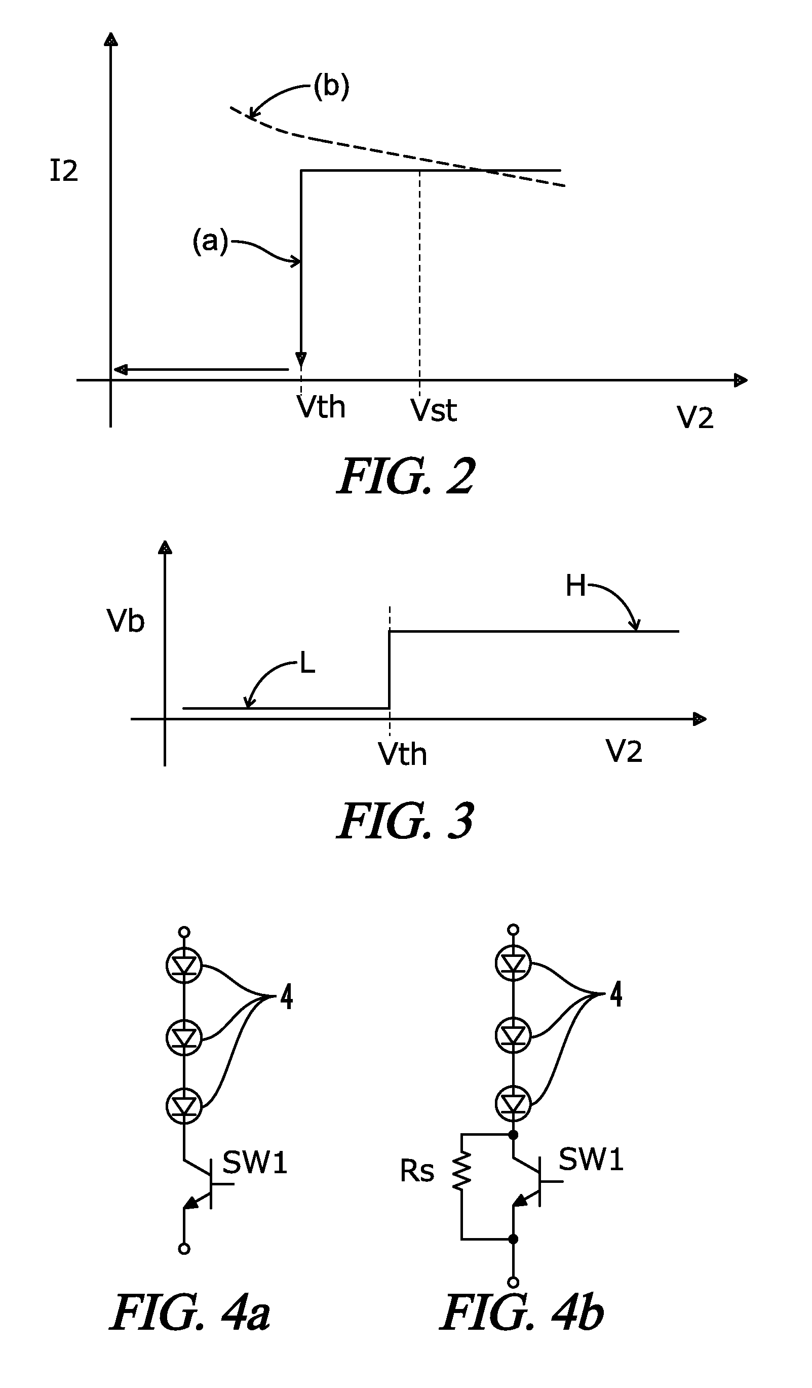
However, if the LED 4 has a short circuit failure (graphically labeled as SC), the constant current control causes a voltage decrease, leaving a problem that a current flowing into the LED 4 cannot be reduced even if the voltage V2 across the LED 4 is decreased due to a short circuit of the LED 4.

Method used


Image

  • LED driver circuit with over-current protection during a short circuit condition
  • LED driver circuit with over-current protection during a short circuit condition
  • LED driver circuit with over-current protection during a short circuit condition

Examples


Embodiment Construction

[0062]Throughout the specification and claims, the following terms take at least the meanings explicitly associated herein, unless the context dictates otherwise. The meanings identified below do not necessarily limit the terms, but merely provide illustrative examples for the terms. The meaning of “a,”“an,” and “the” may include plural references, and the meaning of “in” may include “in” and “on.” The phrase “in one embodiment,” as used herein does not necessarily refer to the same embodiment, although it may. The term “coupled” means at least either a direct electrical connection between the connected items or an indirect connection through one or more passive or active intermediary devices. The term “circuit” means at least either a single component or a multiplicity of components, either active and / or passive, that are coupled together to provide a desired function. The term “signal” means at least one current, voltage, charge, temperature, data or other signal. Where either a f...


PUM


Abstract

An LED driver circuit is provided for protecting one (or more) LEDs connected in series from over-current damages which may result from a short circuit condition. The driver circuit includes a current control circuit for receiving an input signal from a power source and providing a current output for powering the LED. A voltage sensor detects a voltage across the LED. An LED current restriction circuit such as a switching element restricts a current flow into the LED. A short circuit response circuit controls the LED current restriction circuit dependent on a comparison between the voltage detected by the voltage sensor and a predetermined threshold value. When the detected voltage is less than or equal to the threshold value, the response circuit determines a short circuit, and a signal is sent to the current restriction circuit to restrict current flow into the one or more LEDs.

Description

[0001]A portion of the disclosure of this patent document contains material that is subject to copyright protection. The copyright owner has no objection to the reproduction of the patent document or the patent disclosure, as it appears in the U.S. Patent and Trademark Office patent file or records, but otherwise reserves all copyright rights whatsoever.CROSS-REFERENCES TO RELATED APPLICATIONS[0002]This application claims benefit of the following patent application(s) which is / are hereby incorporated by reference: Japan Patent Application No. 2008-300167, filed Nov. 25, 2008.STATEMENT REGARDING FEDERALLY SPONSORED RESEARCH OR DEVELOPMENT[0003]Not ApplicableREFERENCE TO SEQUENCE LISTING OR COMPUTER PROGRAM LISTING APPENDIX[0004]Not ApplicableBACKGROUND OF THE INVENTION[0005]The present invention relates generally to driver circuits for light emitting diodes (referred to as LED hereinafter). More particularly, the present invention relates to LED driver circuits having control circuit...

Claims


Application Information

Patent Timeline
Patent Type & Authority Patents(United States)
IPC IPC(8): H05B41/16H05B44/00
CPCH05B33/089Y02B20/341Y02B20/30H05B45/54
Inventor NAGASE, HARUOKAMBARA, TAKASHI
Owner PANASONIC CORP
Why Eureka
Try Eureka