Rotation speed detection circuit and motor driver apparatus having the same

a detection circuit and motor technology, applied in the direction of motor/generator/converter stopper, electronic commutator, dynamo-electric converter control, etc., can solve the problems of affecting the operation of the motor, reducing the drive efficiency in accordance with the rotation speed of the motor, and unable to perform stable control. , to achieve the effect of stable drive control

Active Publication Date: 2012-09-25
ROHM CO LTD
View PDF8 Cites 6 Cited by
  • Summary
  • Abstract
  • Description
  • Claims
  • Application Information

AI Technical Summary

Benefits of technology

[0008]In view of the above-described problem, an object of the present invention is to provide a rotation speed detection circuit and a motor driver apparatus having the same, which can hardly be affected by a switching noise and can perform stable drive control in accordance with rotation speed of the motor without using a phase current sensing resistor.

Problems solved by technology

In general, in drive control of a brushless motor or the like, a lag may occur in a phase of a drive signal and cause a decrease of drive efficiency in accordance with rotation speed of the motor.
Therefore, they can easily be affected by switching noise and have other problems such as that stable control cannot be performed.

Method used


Image

  • Rotation speed detection circuit and motor driver apparatus having the same
  • Rotation speed detection circuit and motor driver apparatus having the same
  • Rotation speed detection circuit and motor driver apparatus having the same

Examples


first embodiment

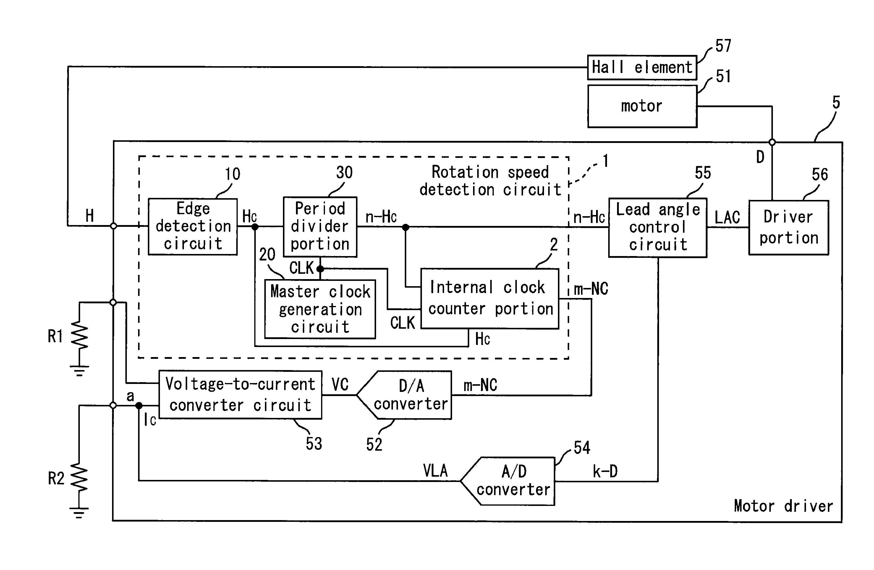
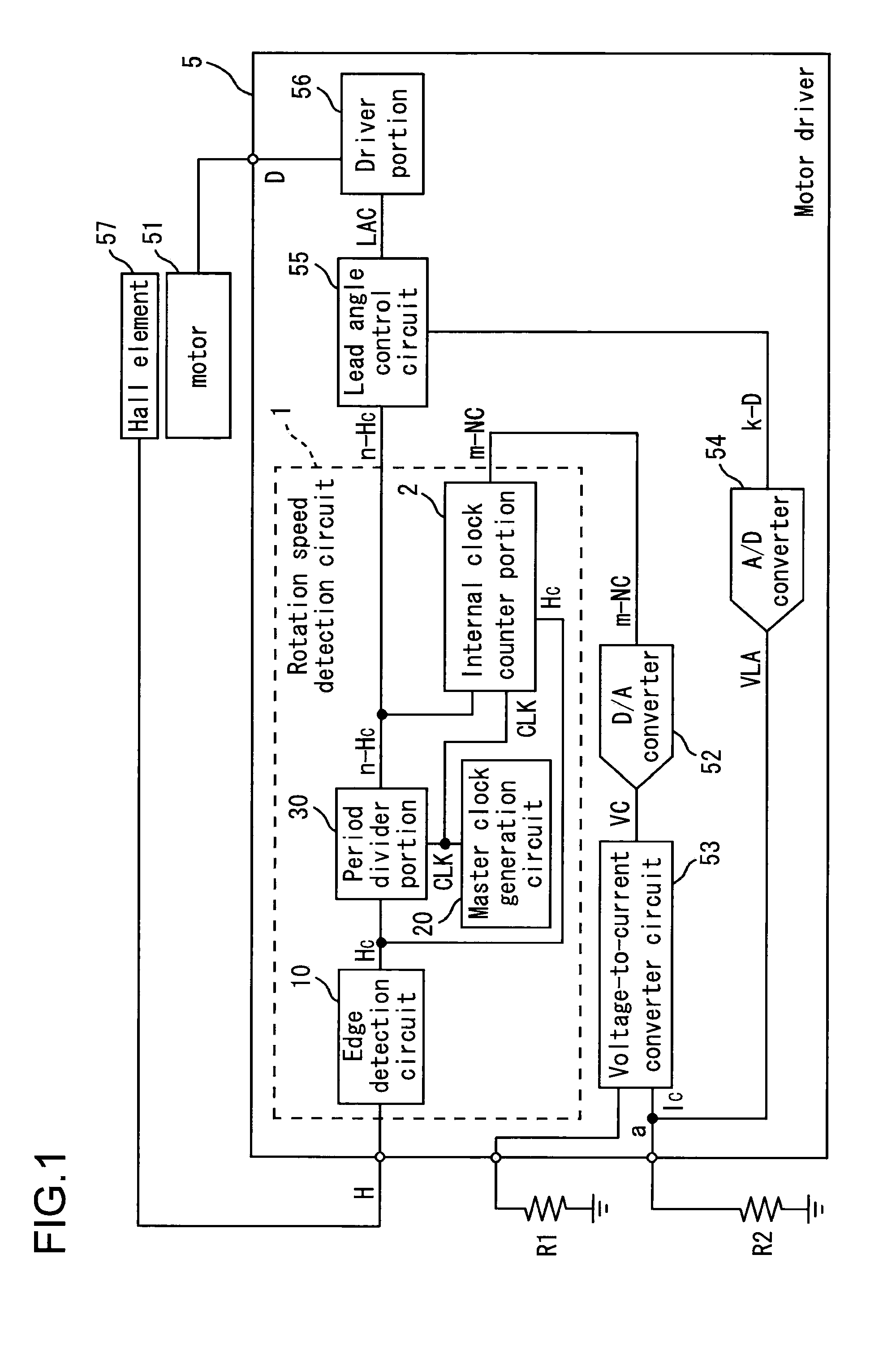
[0020]FIG. 1 is a block diagram illustrating a structure of a rotation speed detection circuit and a motor driver having the same according to a first embodiment. As illustrated in FIG. 1, a motor driver 5 of the first embodiment is a semiconductor integrated circuit device for performing drive control of a motor 51. The motor driver 5 includes a rotation speed detection circuit 1, a D / A converter 52 for converting an L bit digital data signal m-NC output from the rotation speed detection circuit 1 into a first analog voltage signal VC having a first voltage value VC, a voltage-to-current converter circuit 53 for converting the first analog voltage signal VC into an analog current signal IC, an A / D converter 54 for converting a second analog voltage signal VLA having a second voltage value VLA based on the analog current signal IC into a second digital data signal k-D having k bits, a lead angle control circuit 55 for delivering a lead angle control signal LAC for performing lead an...

second embodiment

[0083]In a motor driver 5′ of a second embodiment, set and control of the lead angle value is performed directly by the L bit digital data signal m-NC output from the rotation speed detection circuit 1. Note that an element having the same structure as that in the first embodiment is denoted by the same numeral or symbol, and description thereof will be omitted.

[0084]FIG. 6 is a block diagram illustrating a structure of a rotation speed detection circuit and a motor driver having the same according to the second embodiment. As illustrated in FIG. 6, the motor driver 5′ of the second embodiment is a semiconductor integrated circuit device for performing drive control of the motor 51. The motor driver 5′ includes the rotation speed detection circuit 1, the lead angle control circuit 55 for delivering the lead angle control signal for performing lead angle control of the motor based on the digital data signal and the internal clock signal, and the driver portion 56 for performing the l...

third embodiment

[0090]FIG. 7 is a block diagram illustrating structures of a rotation speed detection circuit and a speed servo function motor driver having the same according to a third embodiment. Note that the element having the same structure as that of the first embodiment is denoted by the same numeral or symbol in the following description.

[0091]As illustrated in FIG. 7, a speed servo function motor driver 7 is a semiconductor integrated circuit device for performing drive control of a motor 71 and includes the rotation speed detection circuit 1, a D / A converter 72 which converts the digital data signal m-NC delivered from the rotation speed detection circuit 1 into the analog voltage signal VC, a voltage-to-current converter circuit 73 which converts the analog voltage signal VC into the analog current signal IC, an acceleration / reduction control pulse signal generation circuit 75 which generates an acceleration control pulse signal AP and a reduction control pulse signal DP so that actual ...


PUM


Abstract

A rotation speed detection circuit includes an internal clock generation portion which receives an input of a period signal whose period varies in accordance with rotation speed of a motor and generates an internal clock signal having a predetermined number of pulses in one period of the period signal, and an internal clock counter portion which counts the number of pulses of the internal clock signal for a predetermined period every one period of the period signal and delivers a count value thereof as a digital data signal.

Description

CROSS-REFERENCE TO RELATED APPLICATIONS[0001]This application is based on Japanese Patent Applications No. 2009-20132 filed on Jan. 30, 2009 and No. 2009-281340 filed on Dec. 11, 2009.BACKGROUND OF THE INVENTION[0002]1. Field of the Invention[0003]The present invention relates to a rotation speed detection circuit of a motor for drive control of the motor and a motor driver apparatus (including a pre-driver) having the same, and particularly to a motor driver apparatus having a phase control function and a speed servo circuit.[0004]2. Description of Related Art[0005]In general, in drive control of a brushless motor or the like, a lag may occur in a phase of a drive signal and cause a decrease of drive efficiency in accordance with rotation speed of the motor. Therefore, control of increasing motor output torque (so-called lead angle control) is usually performed, in which a phase of the drive signal to be supplied to a motor coil is intentionally set to lead a phase of a Hall signal...

Claims


Application Information

Patent Timeline
Patent Type & Authority Patents(United States)
IPC IPC(8): H02P6/00H02P6/06H02P6/08H02P6/15H02P6/17
CPCH02P6/06H02P6/145H02P2203/09H02P6/153
Inventor HIRATA, SHIGERUSHIGMOGAKI, YOSHIFUMI
Owner ROHM CO LTD
Why Eureka
Try Eureka