Eureka AIR delivers breakthrough ideas for toughest innovation challenges, trusted by R&D personnel around the world.

Electronic endoscope signal-processing device and electronic endoscope system

a technology of electronic endoscope and signal processing device, which is applied in the field of signal processing for electronic endoscope system, can solve the problems of insufficient enhancement of features of a target for observation, such as a lesion, and difficulty in emulating a desired spectral image with a linear transformation, so as to achieve the effect of distinguishing blood vessels

Active Publication Date: 2012-09-25
HOYA CORP
View PDF26 Cites 5 Cited by
  • Summary
  • Abstract
  • Description
  • Claims
  • Application Information

AI Technical Summary

Problems solved by technology

However, the image processing disclosed in Japanese Unexamined Patent Publication No. 2006-239206 is complicated, and moreover, it is difficult to emulate a desired spectral image with a linear transformation.
Therefore, features of a target for observation, such as a lesion, may not be sufficiently enhanced.
However, the image processing in Japanese Unexamined Patent Publication No. 2006-239206 cannot effectively distinguish the blood vessels from the surrounding tissue, thus requiring comparison with a normal spectrum image for an appropriate diagnosis.

Method used


Image

  • Electronic endoscope signal-processing device and electronic endoscope system
  • Electronic endoscope signal-processing device and electronic endoscope system
  • Electronic endoscope signal-processing device and electronic endoscope system

Examples


Embodiment Construction

[0015]The present invention is described below with reference to the embodiments shown in the drawings.

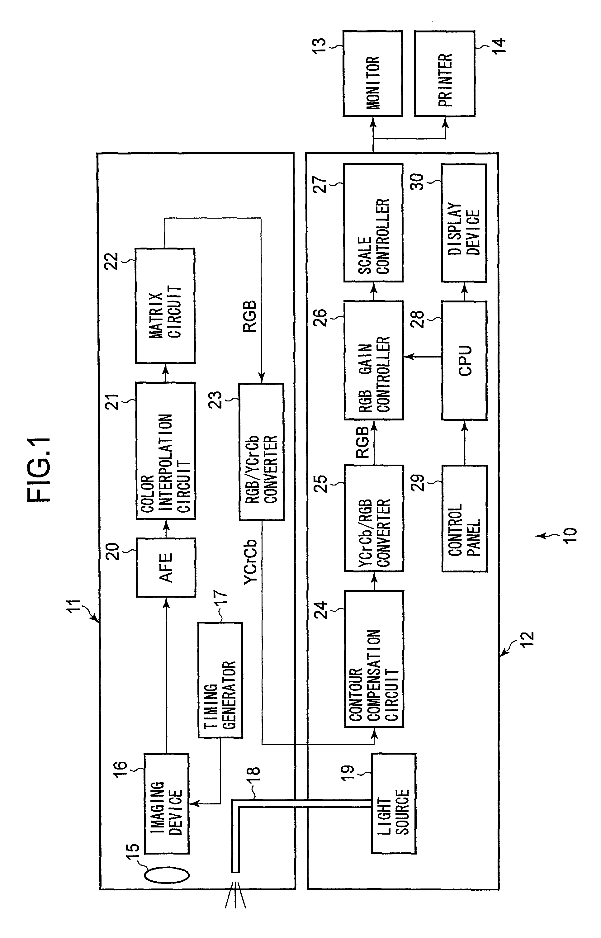
[0016]FIG. 1 is a block diagram schematically illustrating the general structure of an electronic endoscope system of an embodiment to which the present invention is applied.

[0017]As is well know in the art, the electronic endoscope system 10 generally includes a scope portion 11 having a flexible tube for insertion into a body, a processing unit 12 to which the scope portion 11 is detachably attached and that receives image signals from the scope portion 11 to carry out image processing, and output device(s) such as a monitor 13 to display the images from the processing unit 12 and / or a printer 14 to record the images.

[0018]A photographic lens 15 and an imaging device 16 are provided at the distal end of the flexible tube of the scope portion 11. A timing generator 17, which may be provided inside the scope portion 11, drives the imaging device 16. The imaging device 16 captures i...


PUM


Abstract

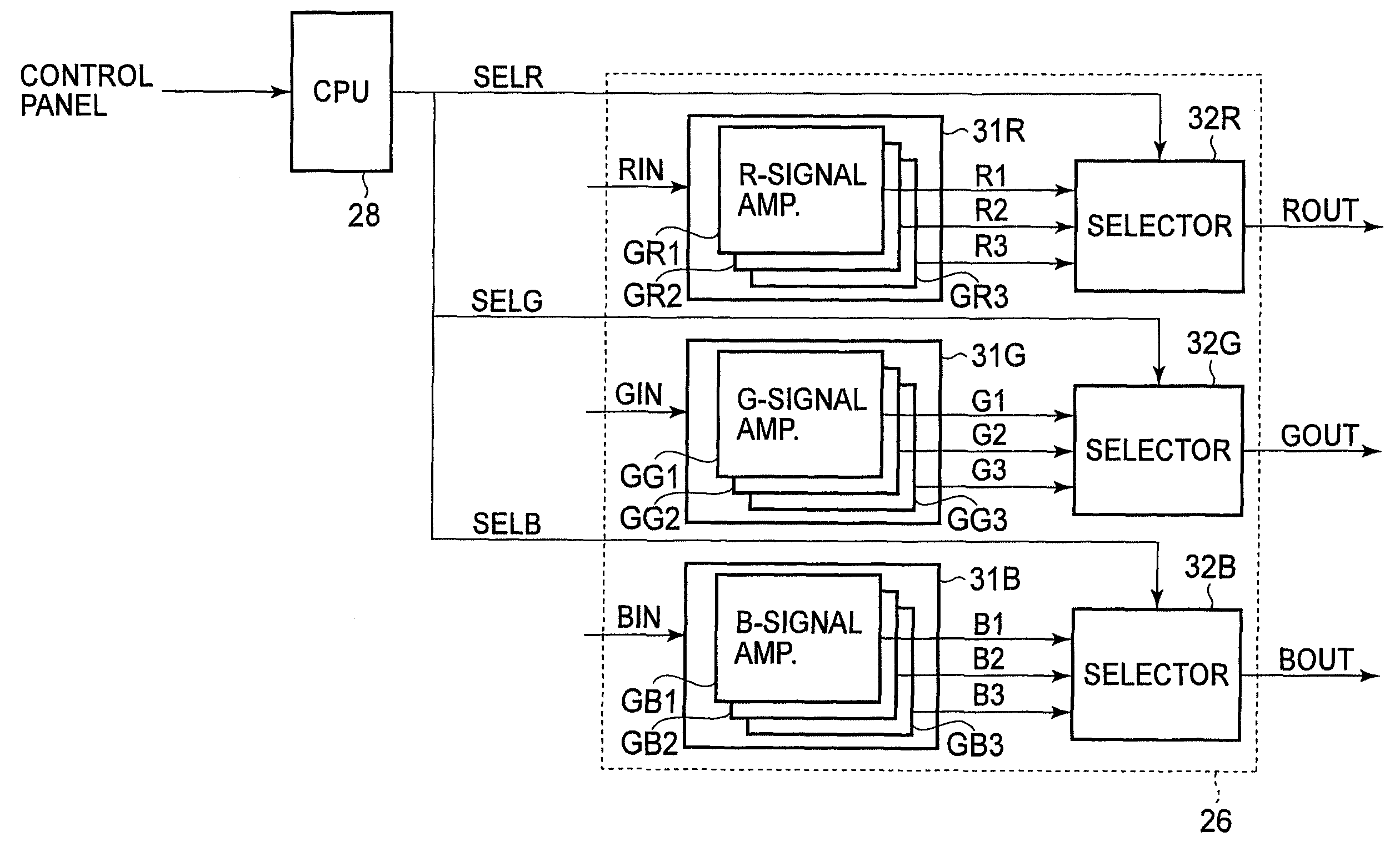
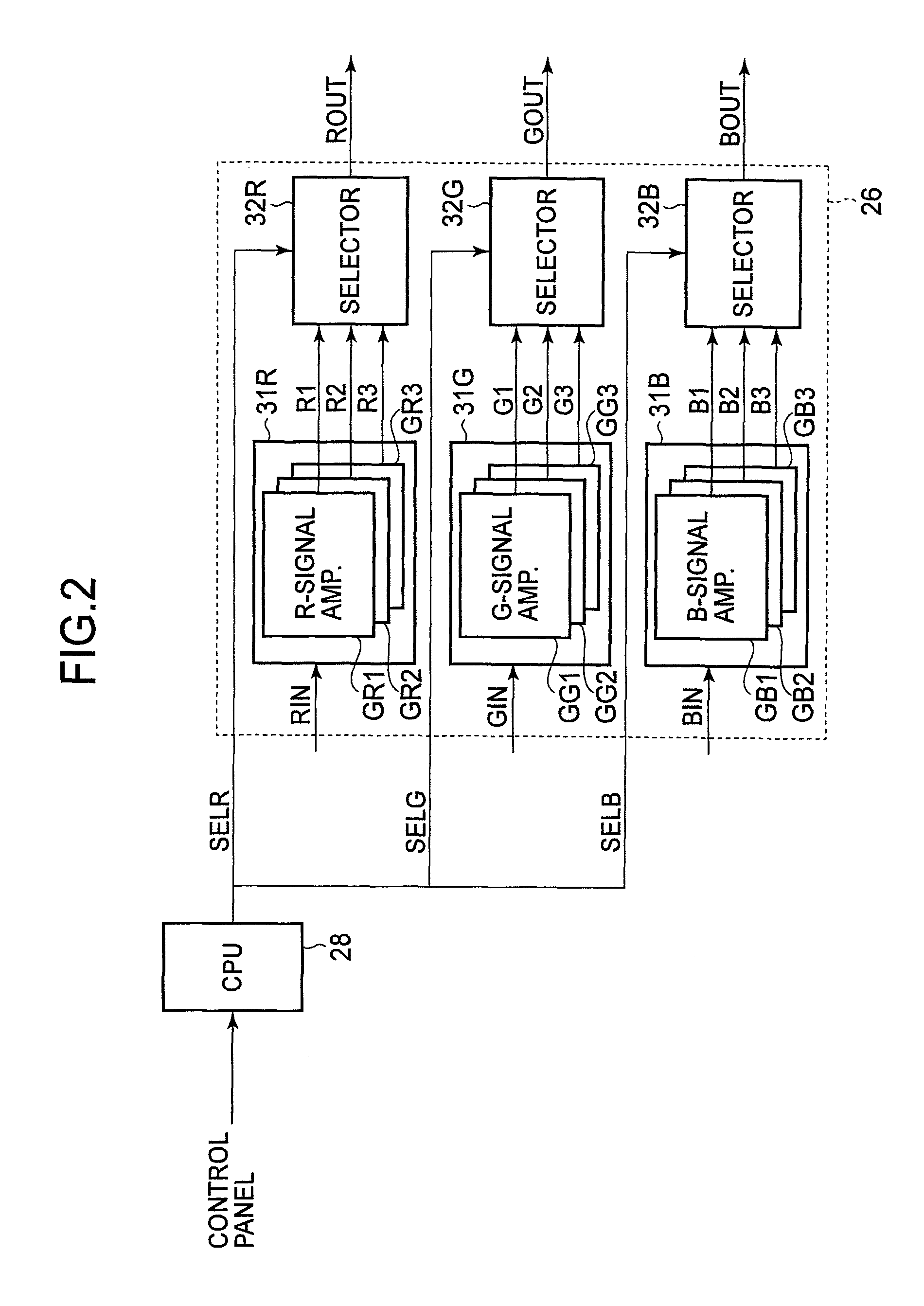
An electronic endoscope system is provided that includes an RGB transformer, an R-signal amplifier, and a GB-signal amplifier. The RGB transformer transforms image signals to RGB signals. The R-signal amplifier changes the amplitude of the R signals of the RGB signals to a predetermined gain value. The GB-signal amplifier nonlinearly changes the amplitude of the G signals and B signals of the RGB signals.

Description

BACKGROUND OF THE INVENTION[0001]1. Field of the Invention[0002]The present invention relates to signal-processing for an electronic endoscope system.[0003]2. Description of the Related Art[0004]There is known an electronic endoscope system that uses narrow band illumination to obtain a spectral image of a particular band for enhancing features such as blood vessels, lesioned areas, and the like, as disclosed in Japanese Unexamined Patent Publication No. 2006-061620. However, the system requires a specialized light source. Thus, this prior art structure raises the cost of the system and is at a disadvantage in carrying out the simultaneous observation of a normal endoscopic image taken with white light. On the other hand, in Japanese Unexamined Patent Publication No. 2006-239206, a spectral image is emulated from the white light by applying a matrix corresponding to the above-mentioned narrow band, to a color transformation matrix which is normally used in image processing.SUMMARY O...

Claims


Application Information

Patent Timeline
Patent Type & Authority Patents(United States)
IPC IPC(8): A62B1/04
CPCA61B1/05G02B23/2476
Inventor TAKAYAMA, SHINICHI
Owner HOYA CORP
Why Eureka
Eureka Blog
Learn More