Linear vibrator with an increased driving force

a technology of linear vibrators and driving forces, applied in mechanical vibration separation, dynamo-electric machines, electrical apparatus, etc., can solve the problems of shortening the life of the commutator, affecting the operation of the commutator, so as to prevent the leakage of magnetic flux and increase the driving force

Active Publication Date: 2012-10-02
MPLUS
View PDF7 Cites 46 Cited by
  • Summary
  • Abstract
  • Description
  • Claims
  • Application Information

AI Technical Summary

Benefits of technology

[0011]The present invention provides a linear vibrator with an increased driving force by preventing the leakage of magnetic flux.

Problems solved by technology

However, the brush type structure using such commutator has a shorter motor life due to mechanical friction and electrical sparks, which cause wear and black powder, as the brush rubs between the segments of commutator when the motor rotates.
Moreover, when voltage is supplied to the motor, it takes time to reach the target magnitude of vibrations by the rotational inertia of the motor.
Thus, it is difficult to realize appropriate vibrations for touchscreen phones.
However, in the linear vibration motor, which is designed to vibrate in the perpendicular direction, the mass installed in the vibration motor is required to secure a vertical displacement within 4 mm of space so as to generate vibrations, so that the space limitation becomes much significant and increasing the amount of vibration may be restricted.

Method used


Image

  • Linear vibrator with an increased driving force
  • Linear vibrator with an increased driving force
  • Linear vibrator with an increased driving force

Examples


Embodiment Construction

[0027]The features and advantages of this invention will become apparent through the below drawings and description.

[0028]A linear vibrator according to certain embodiments of the present invention will be described below in more detail with reference to the accompanying drawings. Those components that are the same or are in correspondence are rendered the same reference numeral regardless of the figure number, and redundant descriptions are omitted.

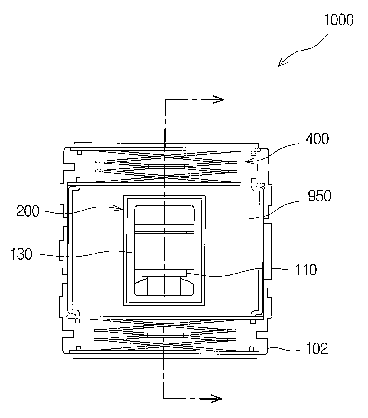
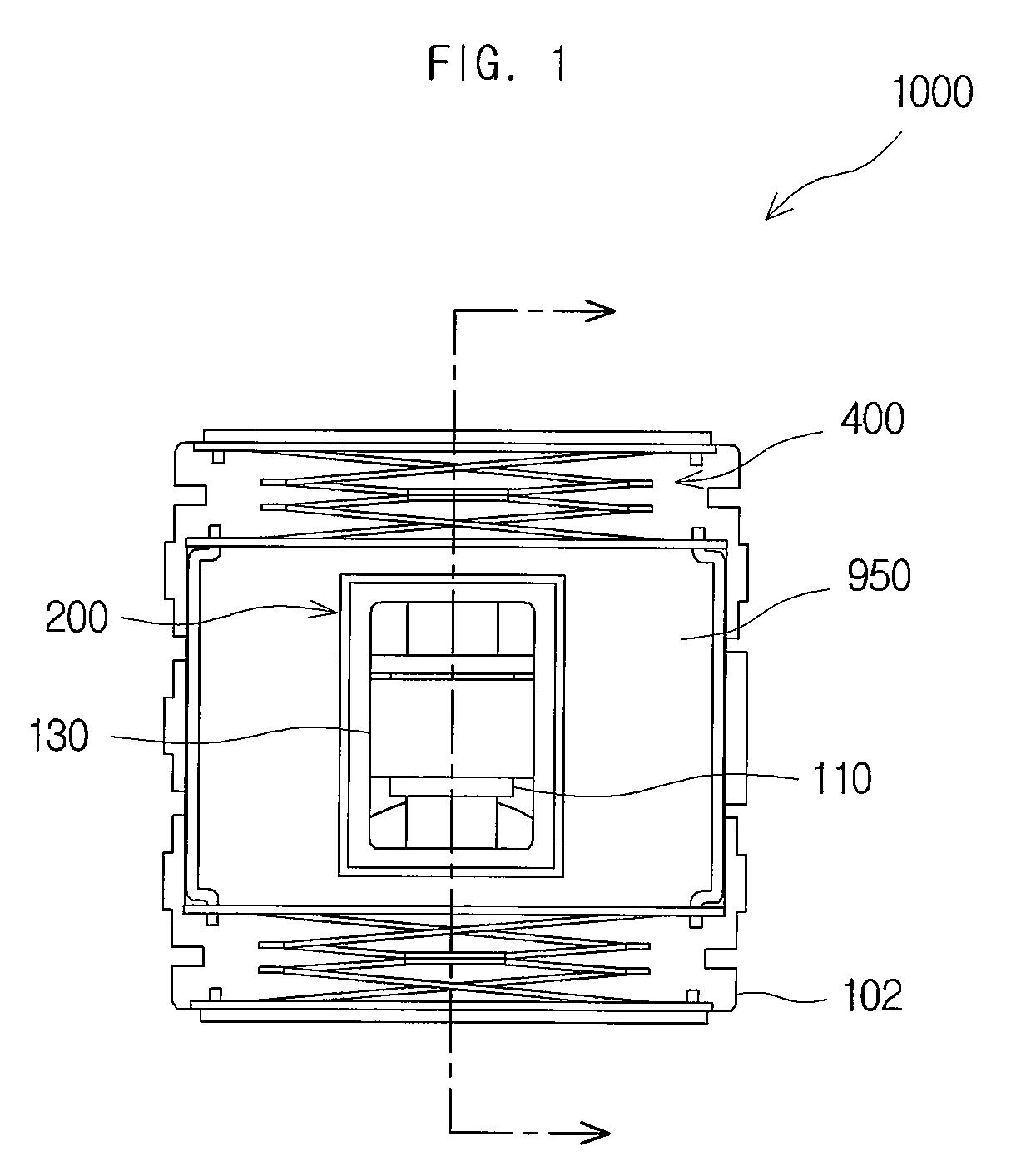
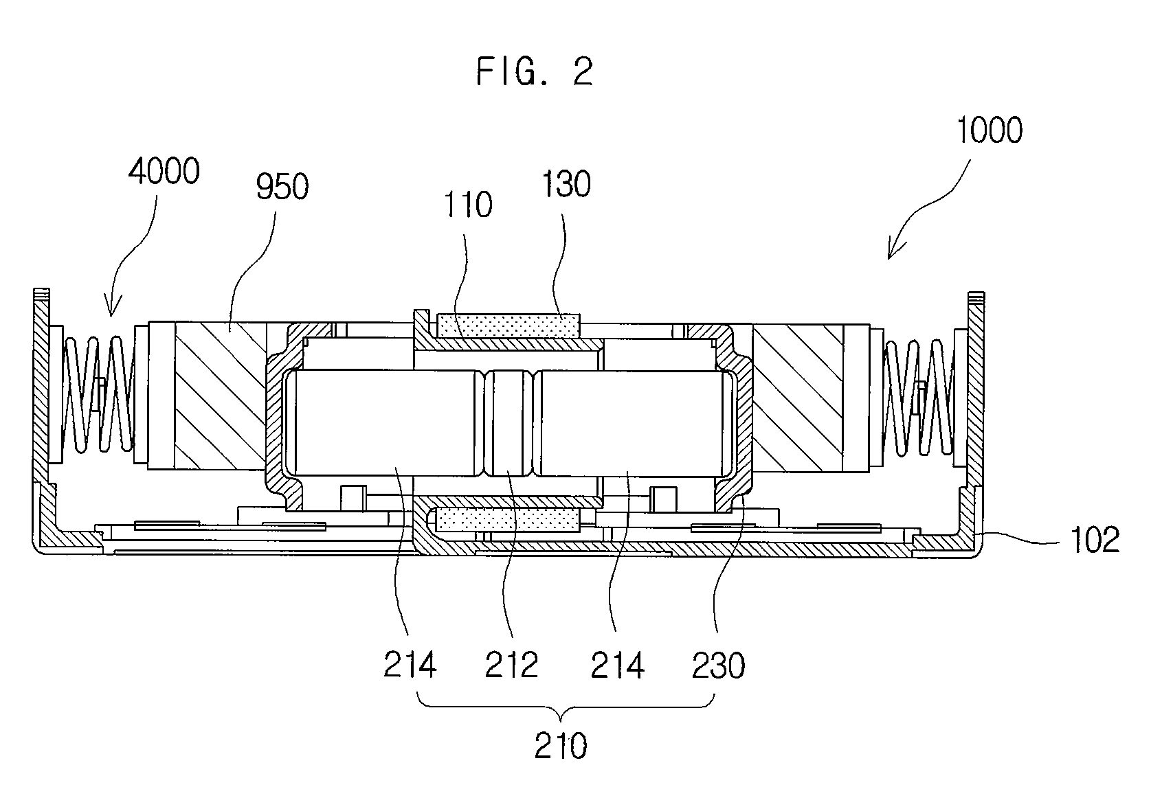
[0029]FIG. 1 is a plan view of a linear vibrator in accordance with an embodiment of the present invention, and FIG. 2 is a cross-sectional view of a linear vibrator in accordance with an embodiment of the present invention. As illustrated in FIGS. 1 and 2, a linear vibrator 1000 in accordance with an embodiment of the present invention can prevent the leakage of magnetic flux caused by a magnet assembly 200 and generate an improved driving force.

[0030]The linear vibrator 1000 can include a base 102, a coil unit 130, a weight 950, a magn...


PUM


Abstract

A linear vibrator is disclosed. The linear vibrator in accordance with an embodiment of the present invention includes a base, a coil unit, which is coupled to the base, a magnet assembly, which forms a closed circuit of a magnetic force perpendicular to an electric current flowing through the coil unit and in which the magnet assembly relatively moves with respect to the coil unit, and an elastic member, which elastically supports the magnet assembly. Thus, a linear vibrator with an increased driving force can be provided by preventing the leakage of magnetic flux.

Description

CROSS-REFERENCE TO RELATED APPLICATIONS[0001]This application claims the benefit of Korean Patent Application No. 10-2009-0104773, filed with the Korean Intellectual Property Office on Nov. 2, 2009, the disclosure of which is incorporated herein by reference in its entirety.BACKGROUND[0002]1. Technical Field[0003]The present invention is related to a linear vibrator.[0004]2. Description of the Related Art[0005]A vibration motor is a part that converts electrical energy into mechanical vibrations by using the principle of generating electromagnetic forces, and is commonly installed in a mobile phone to generate a soundless vibrating alert. With the rapid expansion of mobile phone markets and increased functionalities added to the mobile phone, mobile phone parts are increasingly required to be smaller and better. As a result, there has been an increased demand for the development of a new structure of vibration motor that can overcome the shortcomings of conventional vibration motors...

Claims


Application Information

Patent Timeline
Patent Type & Authority Patents(United States)
IPC IPC(8): H02K33/00
CPCH02K33/16B06B1/045H02K1/146H02K2203/12
Inventor WOO, KI-SUKLEE, KYUNG-HOCHOI, JUN-KUNKIM, YONG-JINOH, HWA-YOUNGBANG, JE-HYUNYOON, YOUNG-BOKPARK, SUCK-JUNLEE, KWANG-HYUNG
Owner MPLUS
Why Eureka
Try Eureka