

Intra-oral measurement device and intra-oral measurement system
a measurement device and intraoral technology, applied in the field of intraoral measurement devices and intraoral measurement systems, can solve the problems of difficult enhancement of measurement accuracy in conventional optical three-dimensional cameras, and achieve the effect of increasing the size of the device and high accuracy
- Summary
- Abstract
- Description
- Claims
- Application Information
AI Technical Summary
Benefits of technology
Problems solved by technology
Method used
Image

Examples
first embodiment
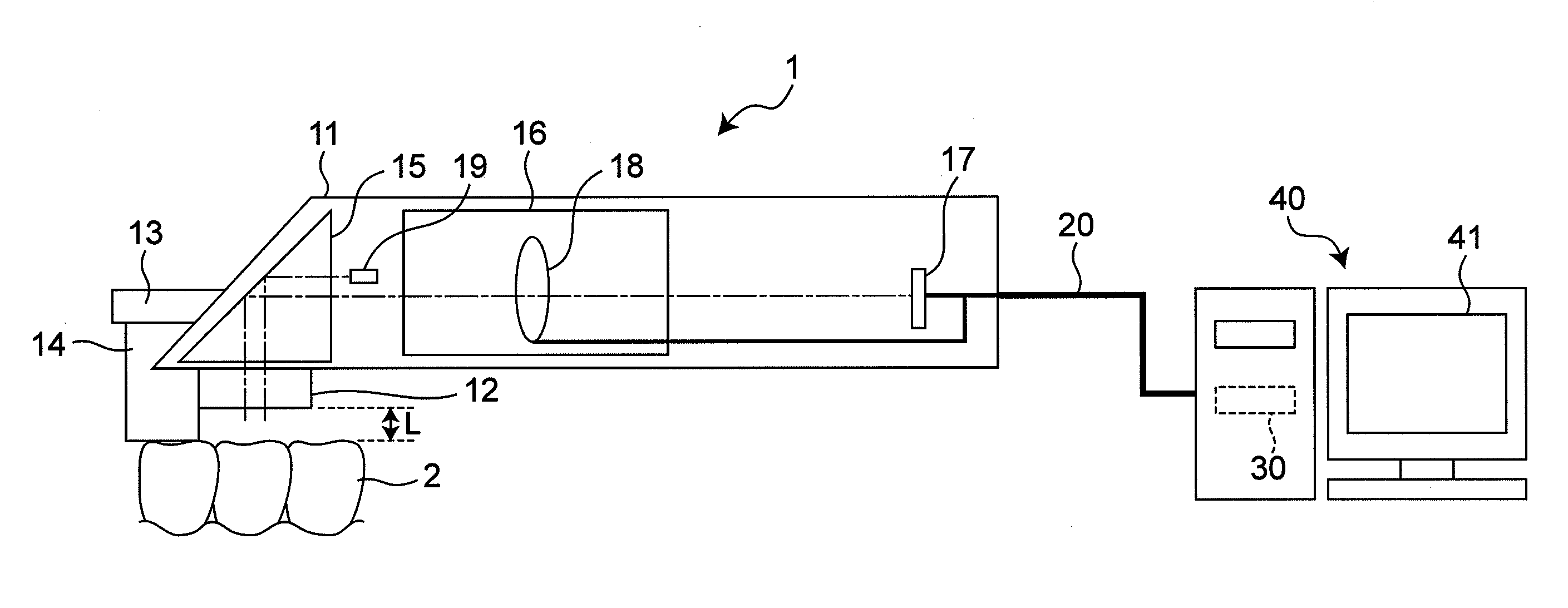
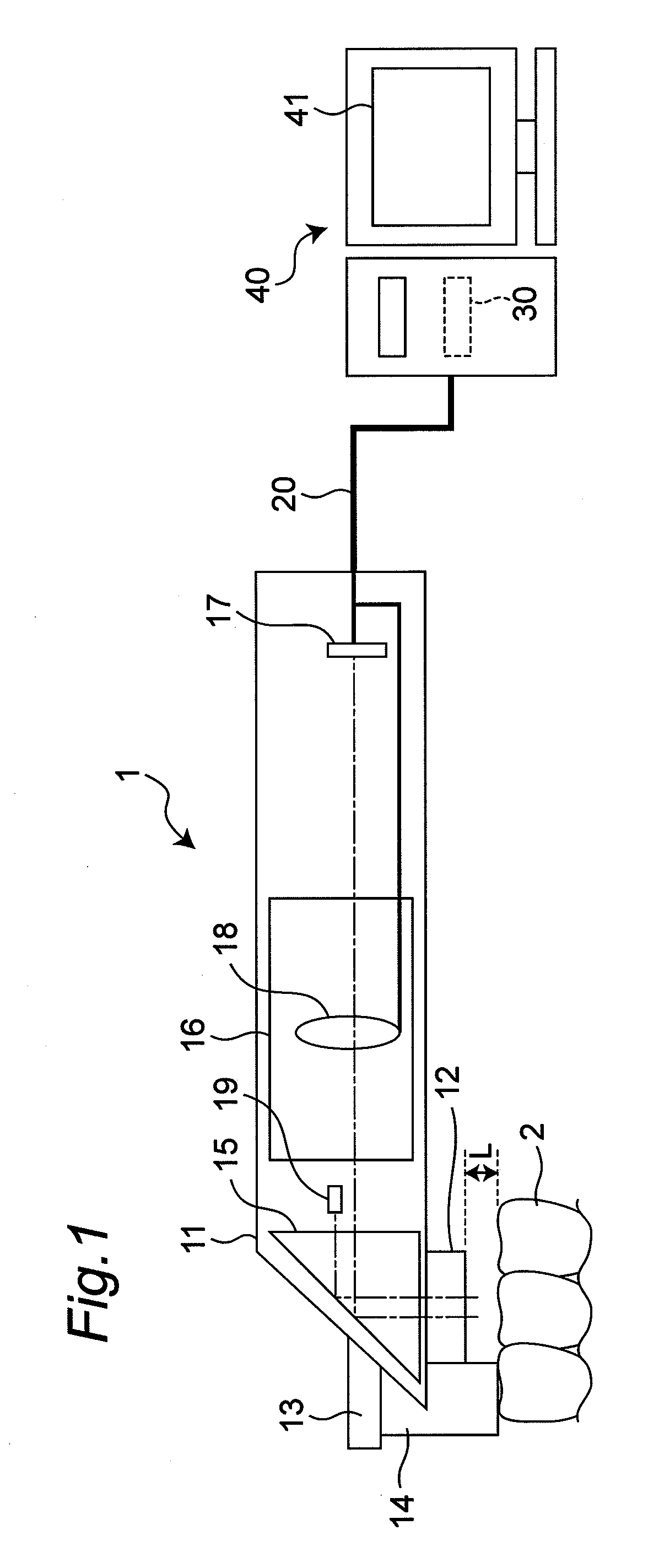
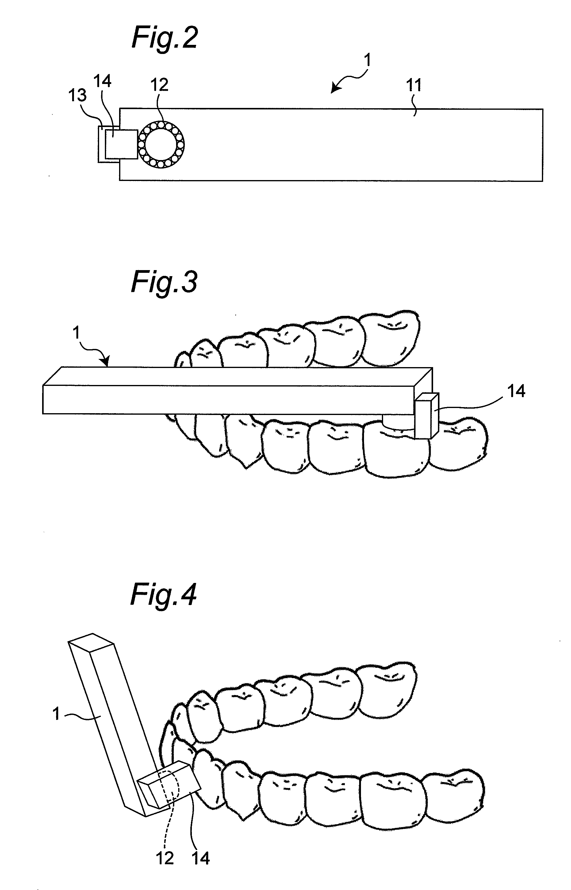
[0053]FIG. 1 is an explanatory view showing a schematic configuration of an intra-oral measurement system including an intra-oral measurement device (hereinafter referred to as oral scanner) according to a first embodiment of the present invention. FIG. 2 is a schematic view of the oral scanner shown in FIG. 1 seen from side.
[0054]As shown in FIG. 1, the oral scanner 1 includes an outer case 11 of a size capable of being directly inserted into an oral cavity of a patient. An outer dimension of the oral scanner 1 is, for example, a length of 200 mm, a width of 20 mm, and a height of 25 mm. A light projecting unit 12 is attached at a distal end portion of the outer case 11 as a light source for clearly taking an image of a measuring object 2 including at least a tooth. A light emitting diode (LED), laser, a halogen lamp, or the like is used for the light projecting unit 12. As shown in FIG. 2, the light projecting unit 12 has a structure in which a plurality of light emitting diodes a...
second embodiment
[0111]FIG. 16 is an explanatory view showing a schematic configuration of an intra-oral measurement system including an oral scanner 1B according to a second embodiment of the present invention. FIG. 17 is a schematic view of the light projecting unit of the oral scanner shown in FIG. 16 seen from downside. The intra-oral measurement system according to the second embodiment differs from the intra-oral measurement system according to the first embodiment in that a light projecting unit 12A including two types of light sources having different wavelengths is arranged in place of the light projecting unit 12, and in that a wavelength control unit (not shown) connected to the image taking control unit 31 is arranged in the image processing unit 30.
[0112]A shape within the oral cavity is different for every patient. The surface reflectivity of light of each tissue differs due to difference in a state of tooth decay, enamel and dentine configuring the tooth, and a composition of the ging...
third embodiment
[0120]FIG. 18 is an explanatory view showing a schematic configuration of an intra-oral measurement system including an oral scanner 1C according to a third embodiment of the present invention. The intra-oral measurement system according to the third embodiment differs from the intra-oral measurement system according to the first embodiment in that a pre-scan light source 71 serving as a pre-scan light projecting device, mirrors 72, 73, and a line sensor 74 are arranged in place of the spot light source 19.
[0121]As described above, since the positioning of the oral scanner 1C is performed by the dentist, the pre-scan surface normally inclines with respect to the irradiation direction of the guide light. In the first embodiment, an inclination angle of the pre-scan surface with respect to the irradiation direction of the guide light is examined by examining the circularity and the like of the guide light. Specifically, the configuration is as described below.
[0122]The pre-scan light ...
PUM
 Abstract
Description
Claims
Application Information