Optical system and image pickup apparatus having same
an optical system and pickup technology, applied in the field of optical systems and image pickup apparatuses, can solve the problems of deterioration in optical performance, insignificant ultraviolet light effect, and difficulty in deposited dielectric antireflection coatings on optical surfaces of optical elements formed of resins, and achieve excellent optical performance and prevent deterioration in optical properties.
- Summary
- Abstract
- Description
- Claims
- Application Information
AI Technical Summary
Benefits of technology
Problems solved by technology
Method used
Image
Examples
first exemplary embodiment
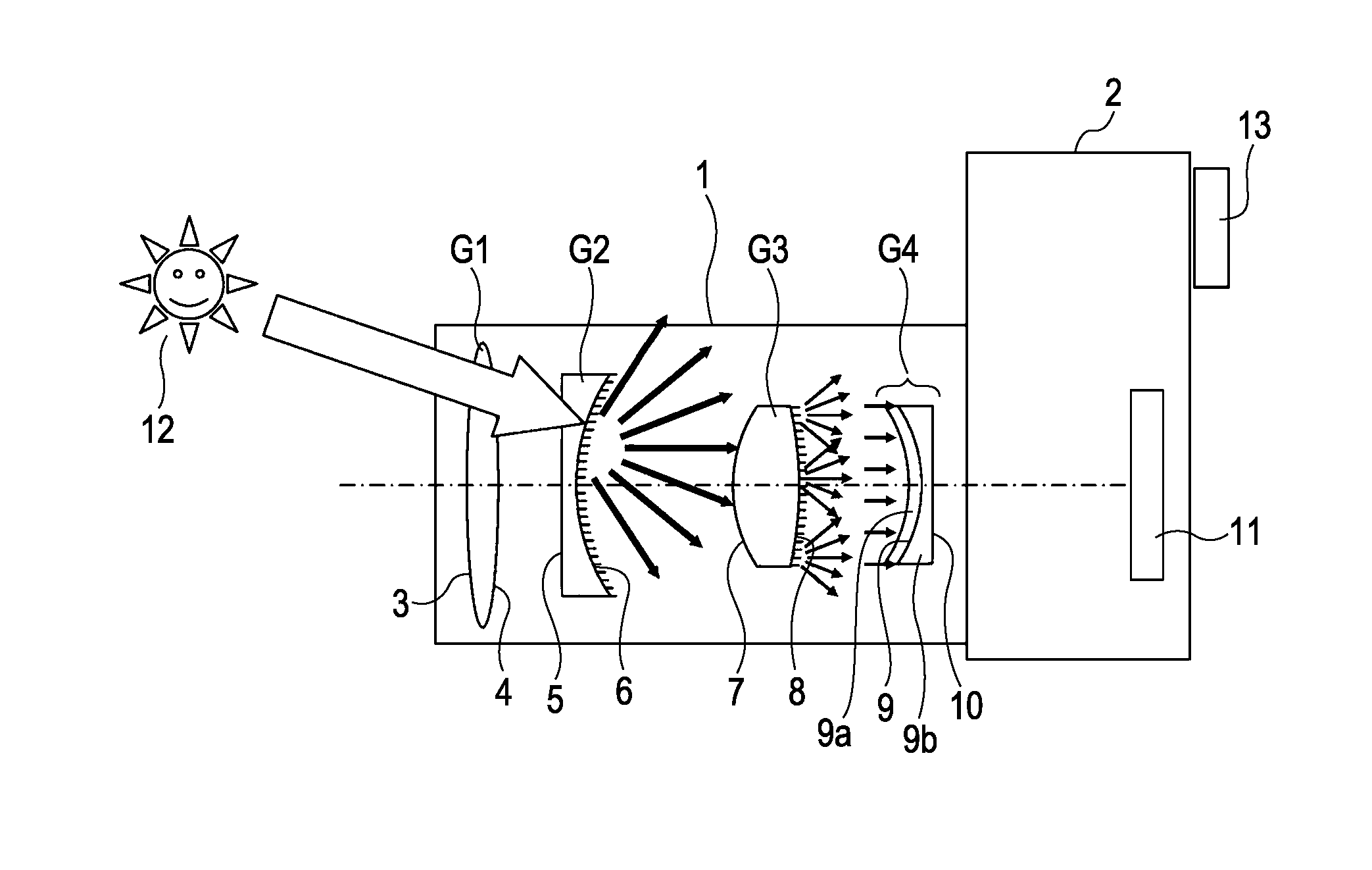
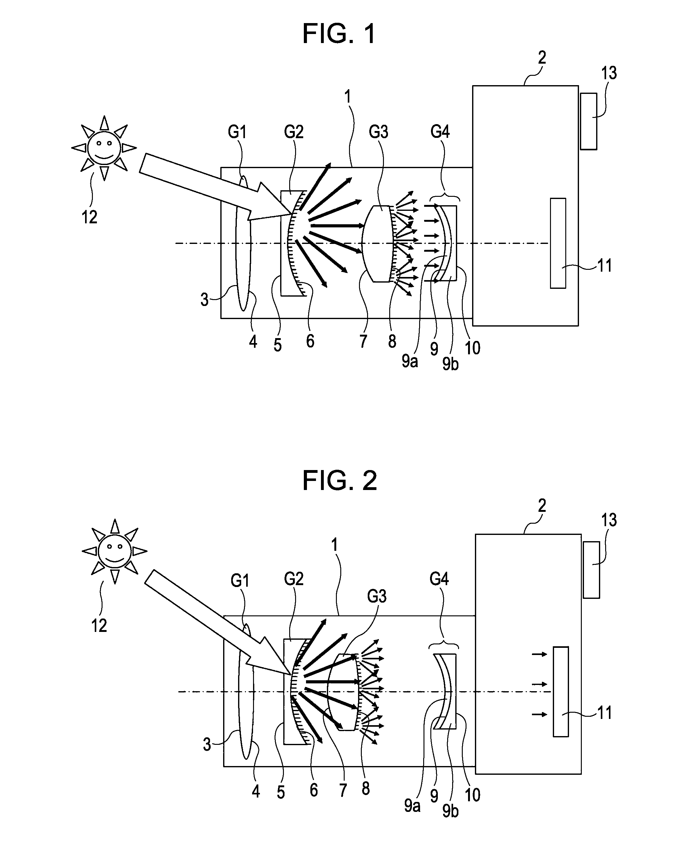
[0057]FIG. 1 is a schematic view of an optical system according to a first embodiment of the present invention. FIG. 2 shows the optical system 1 of FIG. 1 with some lenses moved for focusing or zooming in the direction of the optical axis.
[0058]Reference numeral 1 denotes a photographing optical system. Reference numeral 2 denotes a single-lens reflex camera, to which the photographing optical system 1 is detachably attached.
[0059]Reference letter Gi denotes the ith lens constituting the photographing optical system 1 counting from the object side (light incidence side).
[0060]The photographing optical system 1 of this embodiment includes four lenses: a first lens G1, a second lens G2, a third lens G3, and a fourth lens G4. However, the number of lenses constituting an optical system of the present invention is not limited to four.
[0061]Reference numerals 3 and 4 denote the object side and image side optical surfaces, respectively, of the first lens G1. Reference numerals 5 and 6 de...
second exemplary embodiment
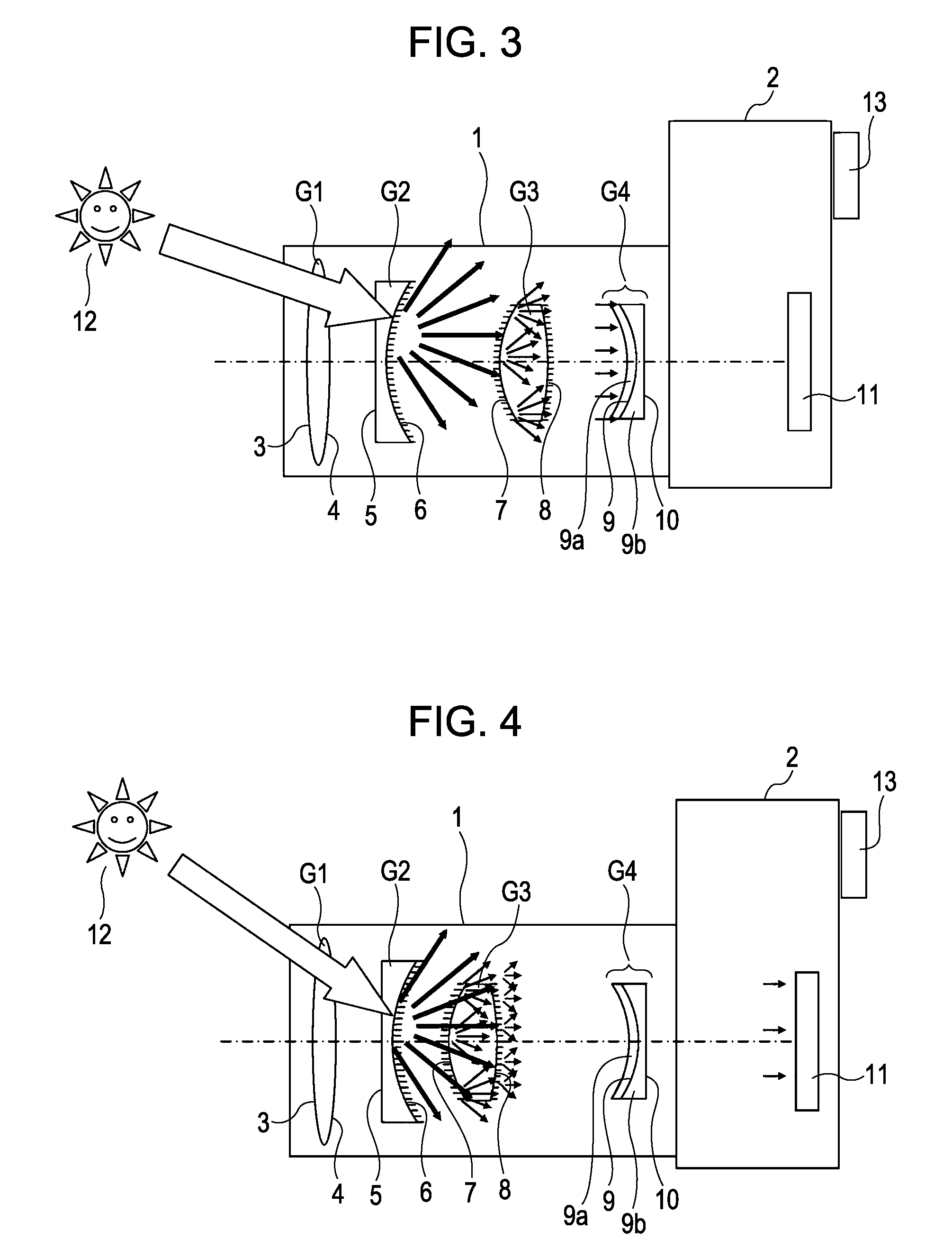
[0083]FIG. 3 is a schematic view of an optical system according to a second embodiment of the present invention.
[0084]FIG. 4 shows the optical system 1 of FIG. 3 with some lenses moved for focusing or zooming in the direction of the optical axis.
[0085]In FIGS. 3 and 4, the same reference numerals are used to designate the same components as those in FIG. 1.
[0086]In the second embodiment, a plurality of depressions or protrusions is formed on each of three of the optical surfaces on the light incidence side of an optical element 9a formed of resin.
[0087]In FIG. 3, as in FIG. 1, reference numeral 1 denotes a photographing lens. Reference numeral 2 denotes a single-lens reflex camera. In the photographing lens 1, reference numerals 3 and 4 denote optical surfaces of the first lens G1. Reference numerals 5 and 6 denote optical surfaces of the second lens G2. Reference numerals 7 and 8 denote optical surfaces of the third lens G3. The fourth lens G4 is a compound aspheric lens. On the in...
third exemplary embodiment
[0098]FIG. 5 is a schematic view of an optical system according to a third embodiment of the present invention.
[0099]In the third embodiment, a plurality of depressions or protrusions is formed on each of three of the optical surfaces on the light incidence side of an optical element 9a formed of resin.
[0100]In FIG. 5, the same reference numerals are used to designate the same components as those in FIG. 1.
[0101]In FIG. 5, as in FIG. 1, reference numeral 1 denotes a photographing lens. Reference numeral 2 denotes a single-lens reflex camera. In the photographing lens 1, reference numerals 3 and 4 denote optical surfaces of the first lens G1.
[0102]Reference numerals 5 and 6 denote optical surfaces of the second lens G2. Reference numerals 7 and 8 denote optical surfaces of the third lens G3. The fourth lens G4 is a compound aspheric lens. On the incidence side of the fourth lens G4, an aspheric layer (optical element) 9a is formed by molding of plastic resin.
[0103]The object side sur...
PUM
| Property | Measurement | Unit |
|---|---|---|
| wavelength | aaaaa | aaaaa |
| wavelength | aaaaa | aaaaa |
| bond energy | aaaaa | aaaaa |
Abstract
Description
Claims
Application Information
 - R&D
- Intellectual Property
- Life Sciences
- Materials
- Tech Scout
- Unparalleled Data Quality
- Higher Quality Content
- 60% Fewer Hallucinations
Browse by: Latest US Patents, China's latest patents, Technical Efficacy Thesaurus, Application Domain, Technology Topic, Popular Technical Reports.
© 2025 PatSnap. All rights reserved.Legal|Privacy policy|Modern Slavery Act Transparency Statement|Sitemap|About US| Contact US: help@patsnap.com


