Energy management of HVAC system

a technology for energy management and hvac systems, applied in mechanical power/torque control, program control, electric devices, etc., can solve the problems of lack of active control and shortage of electric generating capacity of many utilities, and achieve the effect of reducing the power consumption of the hvac system

Active Publication Date: 2012-10-02
HAIER US APPLIANCE SOLUTIONS INC
View PDF23 Cites 99 Cited by
  • Summary
  • Abstract
  • Description
  • Claims
  • Application Information

AI Technical Summary

Benefits of technology

[0005]According to one aspect, an HVAC system for conditioning air of an associated room comprises one or more power consuming features / functions including at least one temperature controlling element for one of heating and cooling air. A controller is operatively connected to the one or more power consuming features / functions. The controller is configured to receive and process a signal indicative of a utility state. The controller operates the HVAC system in one of a plurality or operating modes, including at least a normal operating mode and an energy savings mode in response to the received signal. The controller is configured to at least one of selectively adjust and deactivate at least one of the one or more power consuming features / functions to reduce power consumption of the HVAC system in the energy savings mode.

Problems solved by technology

Many utilities are currently experiencing a shortage of electric generating capacity due to increasing consumer demand for electricity.
Currently utilities generally charge a flat rate, but with increasing cost of fuel prices and high energy usage at certain parts of the day, utilities have to buy more energy to supply customers during peak demand.
This is undesirable because the consumer may not always be present in the home to operate the system during off-peak hours.
This is also undesirable because the consumer is required to manually track the current time to determine what hours are off-peak and on-peak.
However, there is no active control beyond the mere on / off switching.

Method used


Image

  • Energy management of HVAC system
  • Energy management of HVAC system
  • Energy management of HVAC system

Examples


Embodiment Construction

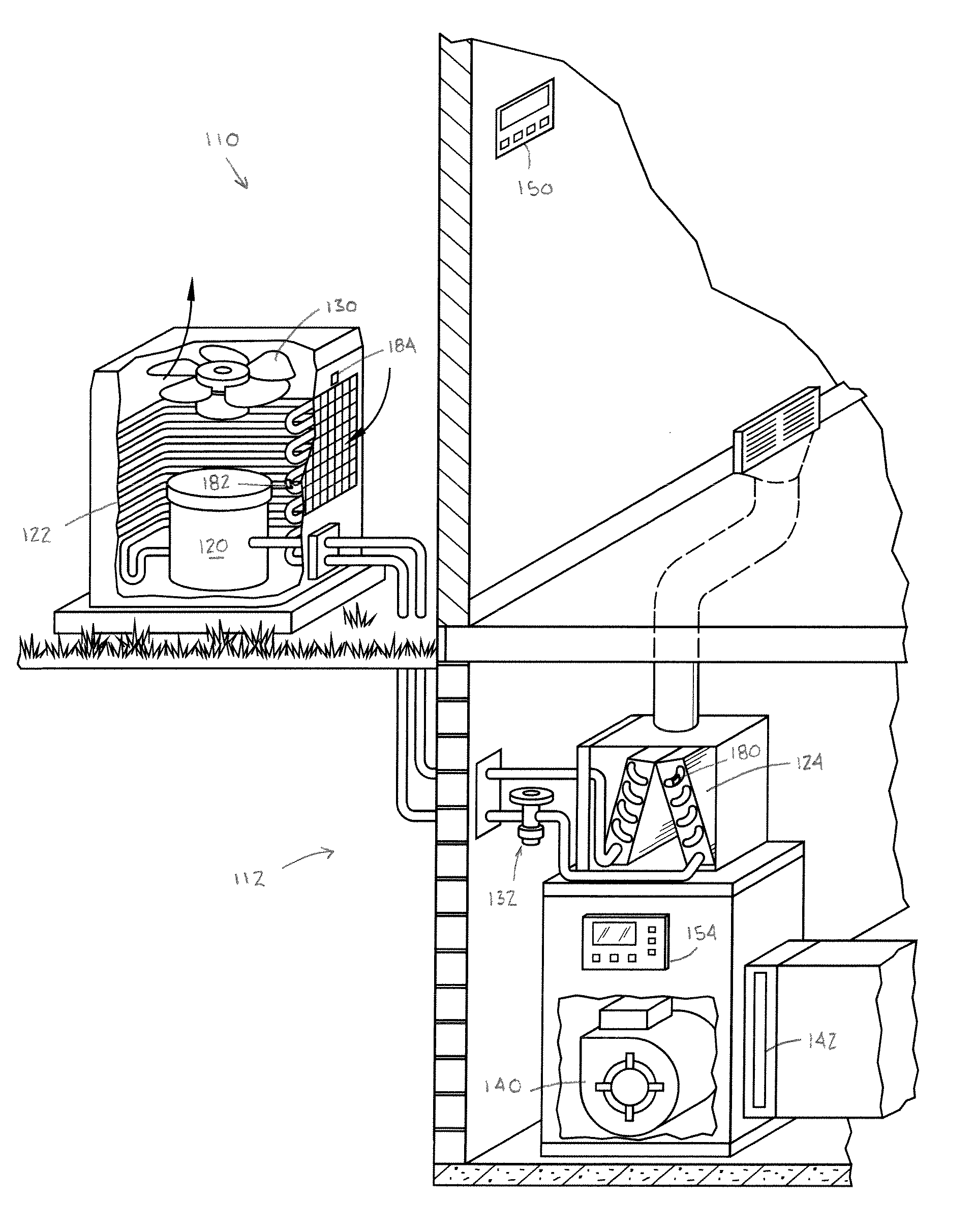
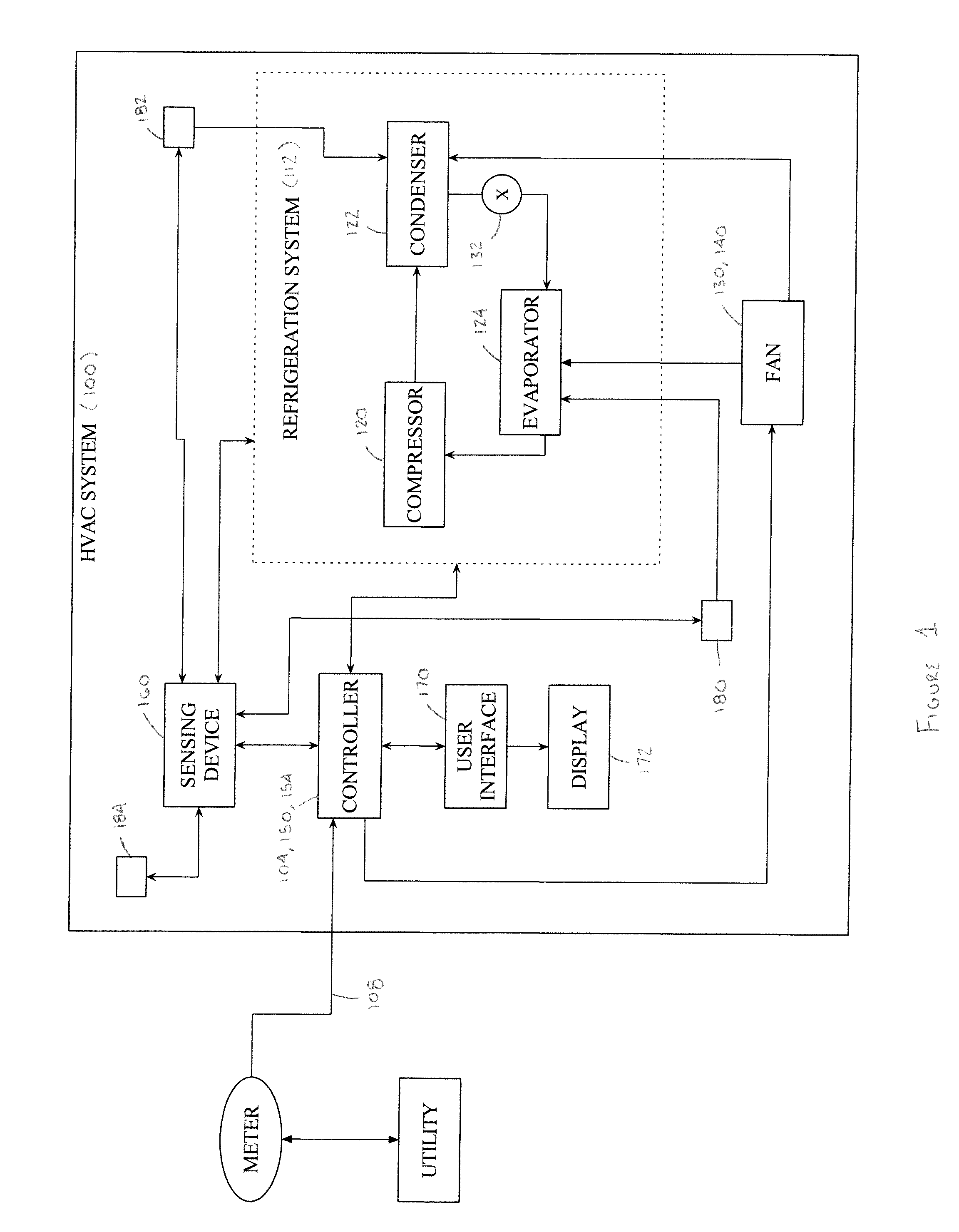
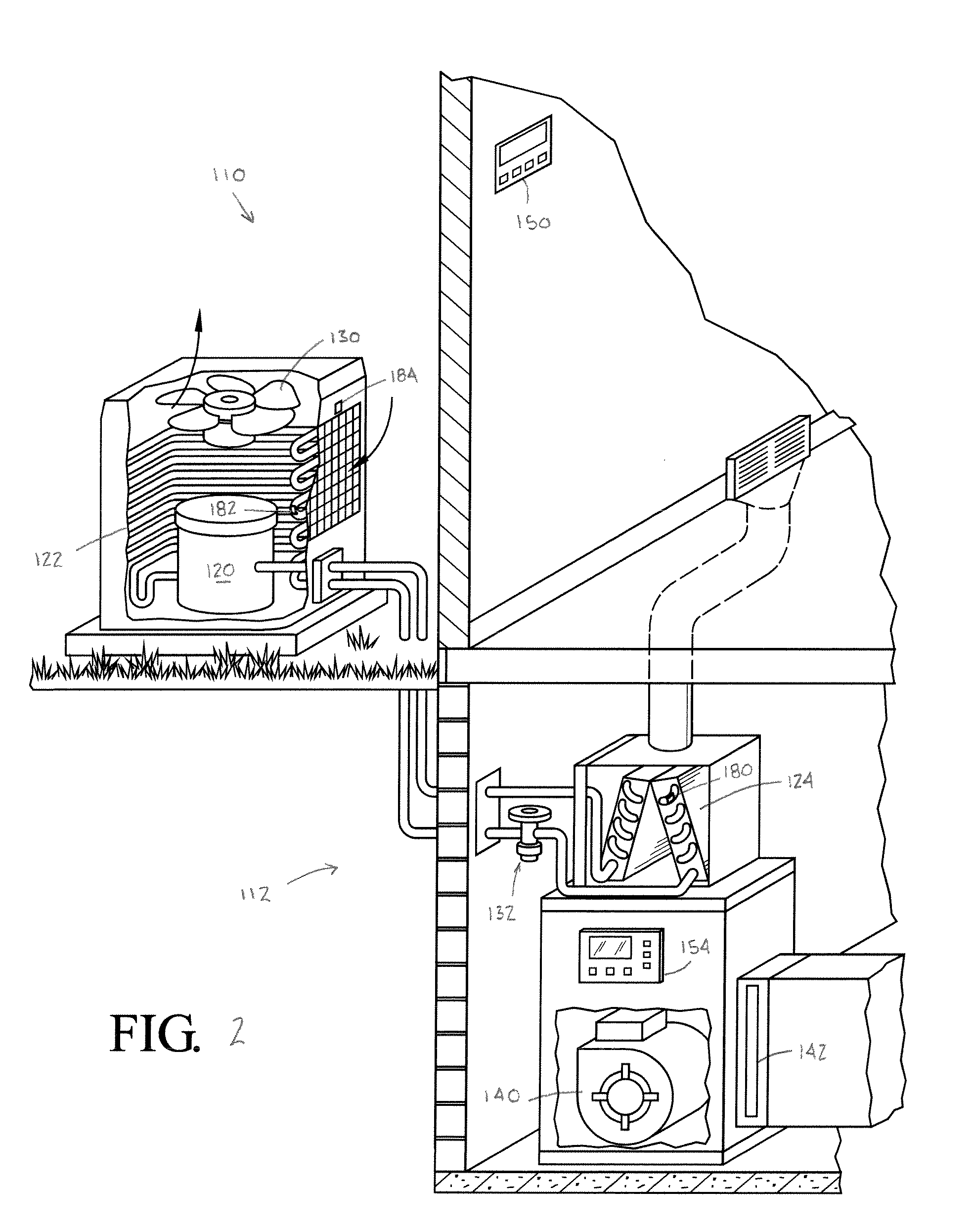
[0012]It should, of course, be understood that the description and drawings herein are merely illustrative and that various modifications and changes can be made in the structures disclosed without departing from the present disclosure. Referring now to the drawings, wherein like numerals refer to like parts throughout the several views, FIG. 1 schematically illustrates a HVAC system 100 for conditioning air of a room according to one aspect of the present disclosure. The HVAC system 100 comprises one or more power consuming features / functions including at least one temperature controlling element for one of heating and cooling air. A controller 104 is operatively connected to each of the power consuming features / functions. The controller 104 can include a micro computer on a printed circuit board which is programmed to selectively control the energization of the power consuming features / functions. The controller 104 is configured to receive and process a signal 108 indicative of a ...


PUM

PropertyMeasurementUnit
temperatureaaaaaaaaaa
power consumptionaaaaaaaaaa
temperaturesaaaaaaaaaa

Abstract

An HVAC system for conditioning air of an associated room includes one or more power consuming features / functions including at least one temperature controlling element for one of heating and cooling air. A controller is operatively connected to the one or more power consuming features / functions. The controller is configured to receive and process a signal indicative of a utility state. The controller operates the HVAC system in one of a plurality or operating modes, including at least a normal operating mode and an energy savings mode in response to the received signal. The controller is configured to at least one of selectively adjust and deactivate at least one of the one or more power consuming features / functions to reduce power consumption of the HVAC system in the energy savings mode.

Description

BACKGROUND[0001]The present disclosure relates to energy management, and more particularly to power consuming device control methods and electrical energy consumption systems. This disclosure finds particular application to energy management of HVAC systems, such as central air conditioning systems for a home or office building.[0002]Many utilities are currently experiencing a shortage of electric generating capacity due to increasing consumer demand for electricity. Currently utilities generally charge a flat rate, but with increasing cost of fuel prices and high energy usage at certain parts of the day, utilities have to buy more energy to supply customers during peak demand. Consequently, utilities are charging higher rates during peak demand. If peak demand can be lowered, then a potential huge cost savings can be achieved and the peak load that the utility has to accommodate is lessened. In order to reduce high peak power demand, many utilities have instituted time of use meter...

Claims


Application Information

Patent Timeline
Patent Type & Authority Patents(United States)
IPC IPC(8): G05B21/00G05D23/32G05D3/12G05D5/00G05D9/00G05D11/00G05D17/00G01R11/56G01R21/133G05B13/00G05B15/00G01M1/38F24F11/00G05D23/19F25B29/00F28F13/00B60H1/00H04Q9/06G06F17/00G01K13/00F25D17/00C12Q1/68
CPCG05B15/02G05B2219/2642
Inventor BESORE, JOHN K.FINCH, MICHAEL F.WORTHINGTON, TIMOTHY DALECAPELLE, DANIEL RYAN
Owner HAIER US APPLIANCE SOLUTIONS INC
Why Eureka
Try Eureka