Self priming intravenous delivery system

a technology of self-priming and intravenous delivery, which is applied in the direction of intravenous devices, suction devices, other medical devices, etc., can solve the problems of affecting the delivery process, so as to achieve the effect of complete removal of air bubbles and time-consuming processes

Active Publication Date: 2012-10-09
BECTON DICKINSON & CO
View PDF27 Cites 7 Cited by
  • Summary
  • Abstract
  • Description
  • Claims
  • Application Information

AI Technical Summary

Benefits of technology

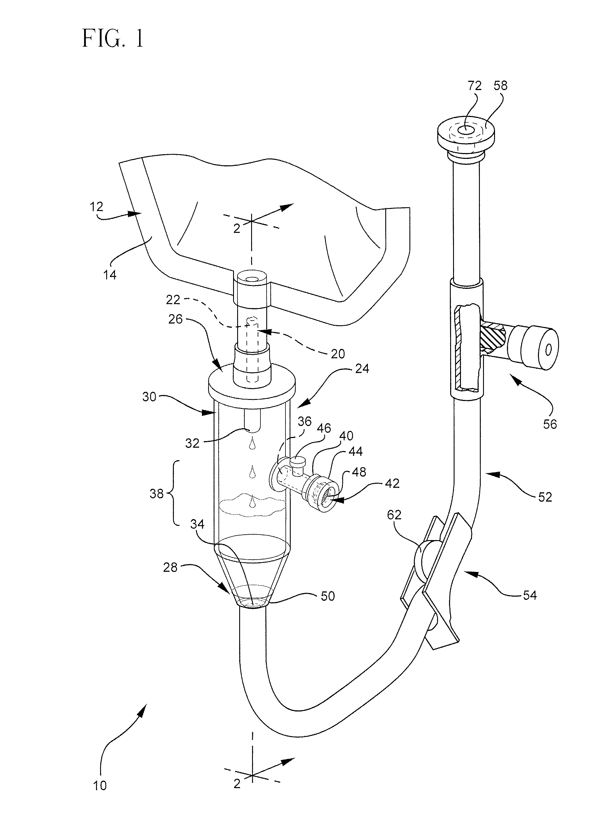
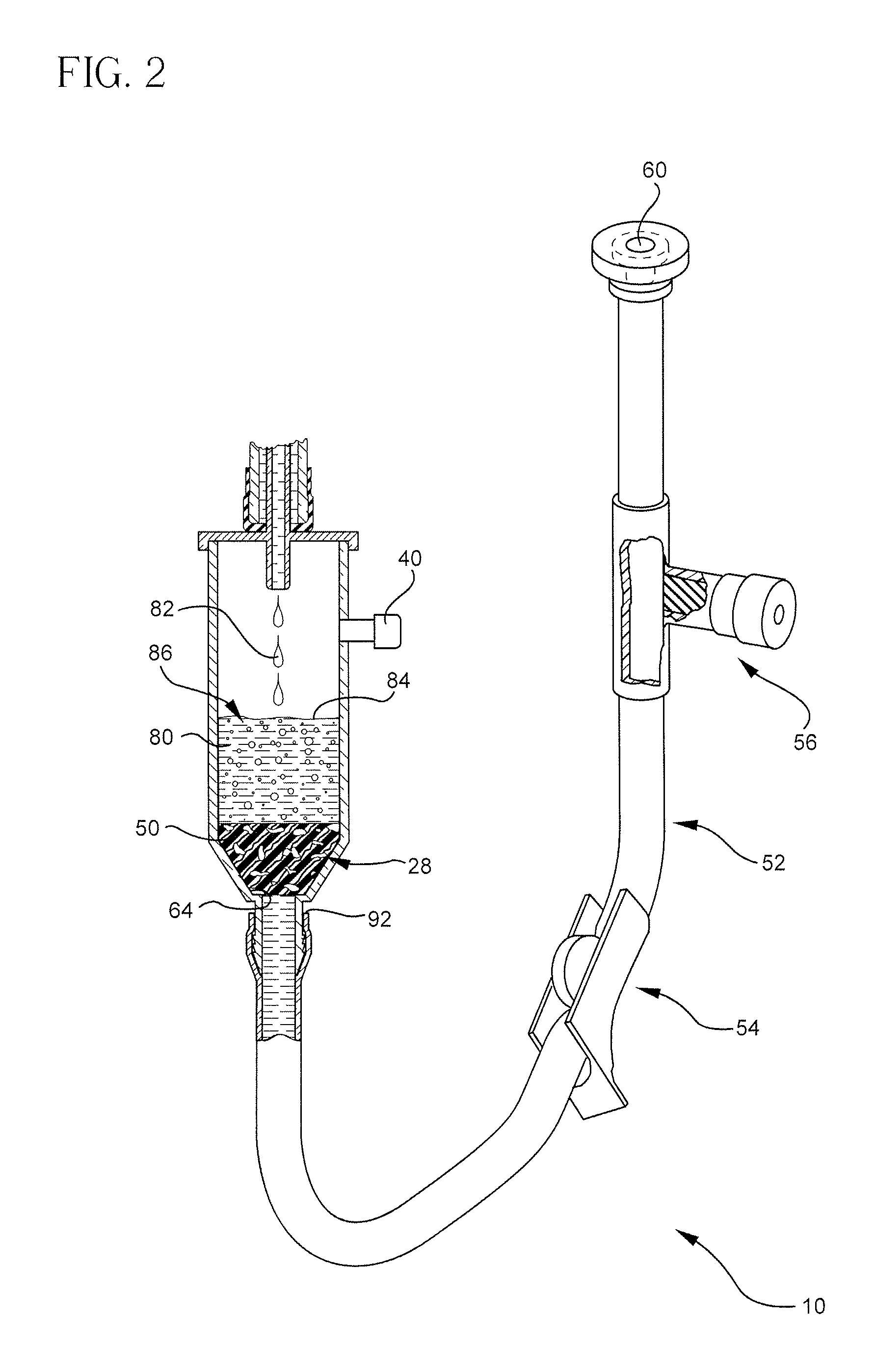
[0017]Additionally, the IV set may include a means for venting air out of the patient conduit tube, such a flow control plug that has an air vent coupled to the outlet end of the patient conduit. The flow control plug may include a hydrophobic material, which allows air to exit the IV set while preventing liquid from exiting. The air vent may also include several small holes which allow air to pass while limiting the passage of liquid through the end plug. The end plug and the air vent acts as a flow restrictor to the exiting air, so that when a liquid is moving through the tube, the velocity of the liquid flow is controlled such that the flow is generally laminar. The laminar flow of the liquid through the tube prevents air from becoming entrapped within the tube during priming and helps to completely eliminate the air from the tube during priming.
[0019]Where the active portion of the bubble isolation device or membrane includes a hydrophilic filter or an absorbent structure, the bubble isolation device may be shaped to match the profile and abuts the bottom surface of the drip chamber so that the active portion completely covers the chamber outlet. By disposing the bubble isolation device against the bottom surface of the drip chamber, air is prevented from being trapped between the bubble isolation device and the bottom surface of the drip chamber.
[0021]The IV set may also include a particulate filter to prevent solid material from exiting the tube. Additionally, the IV set may include a zero dead space access port disposed between the inlet end and the outlet end of the tube. A zero dead space access port is designed to substantially prevent the entrapment of air within the access port as liquid flows through the access port.
[0023]A method for priming the IV set described above may include the steps of coupling the chamber inlet to a source of the liquid, wetting the bubble isolation device with liquid, and using the bubble isolation device to prevent air bubbles from reaching the chamber outlet. Additionally, the method may include the steps of opening the clamp to permit liquid to flow through the tube, using the end plug to restrict the venting of air from the tube as liquid flows through the tube so that the fluid flow through the tube is laminar, and using the end plug to prevent liquid from exiting the outlet end of the tube.

Problems solved by technology

Specifically, if air bubbles are allowed to enter a patient's blood stream while receiving the intravenous administration of liquids, the air bubbles can form an air embolism and cause serious injury to a patient.
As a result, these air bubbles may cause strokes, tissue damage, and / or death.
In spite of the importance of removing air bubbles while priming an IV set for use in the intravenous administration of liquids, the complete removal of air bubbles can be a time consuming process.
The process may also lead to contamination of the IV set by inadvertently touching a sterile end of the IV set.
This initial process, however, typically traps air in tubing which must be removed.
This can cause a bubble ladder to form as air is sucked from the drip chamber into the tubing.
This problem may be aggravated in pediatric applications where the drip orifice may be smaller which may result in increased turbulence.
During this procedure the end of the tubing may contact the waste basket or be touched by the attendant and thus, become contaminated.
However, the bubbles formed from the dripping action may become trapped on the filter, thus, reducing the flow of liquid through the filter to the IV tubing.
However, the filter is normally positioned so that air may be trapped between the bottom of the filter and the bottom of the drip chamber.

Method used


Image

  • Self priming intravenous delivery system
  • Self priming intravenous delivery system
  • Self priming intravenous delivery system

Examples


Embodiment Construction

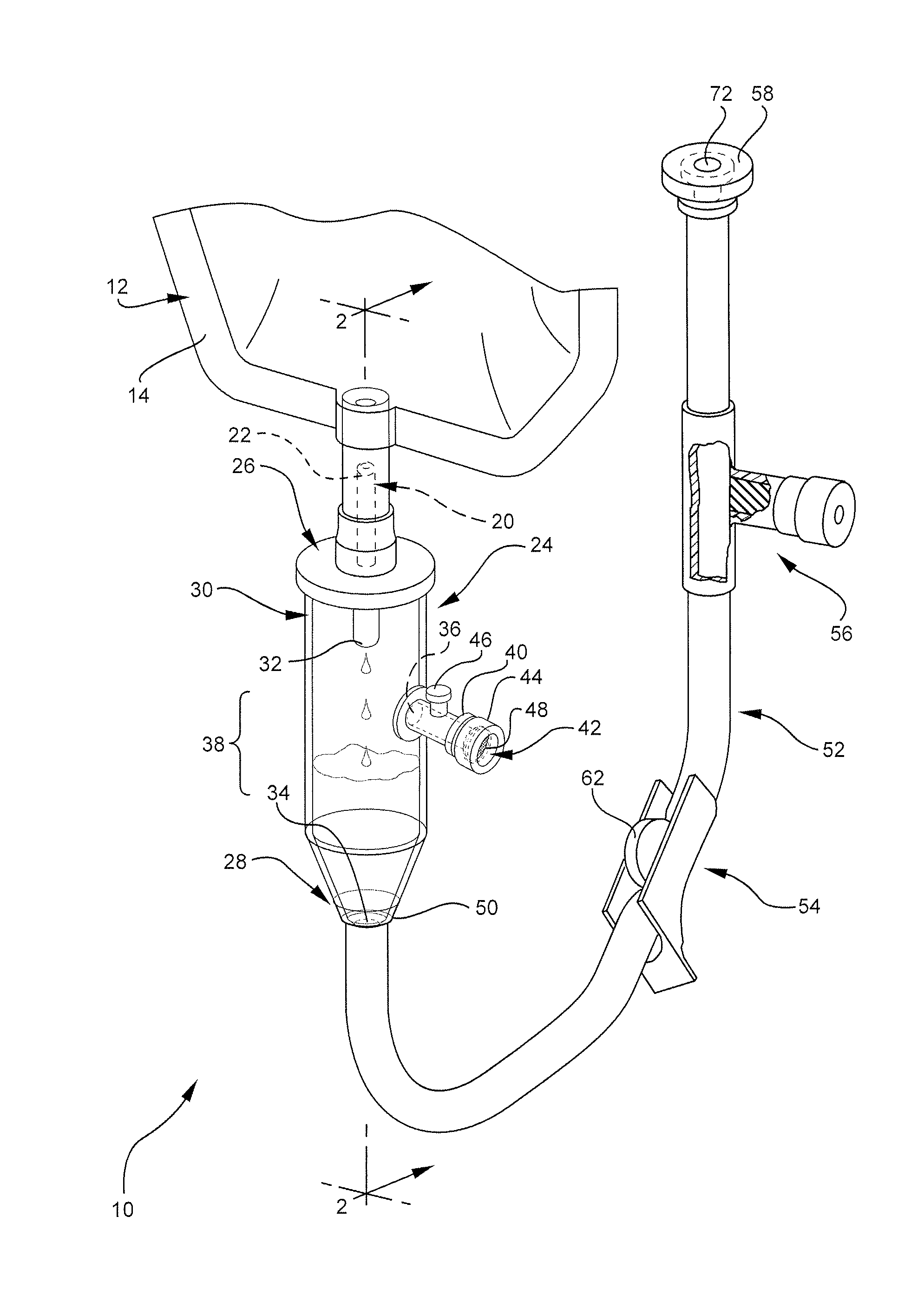
[0032]The presently preferred embodiments of the present invention will be best understood by reference to the drawings, wherein like parts are designated by like numerals throughout. It will be readily understood that the components of the present invention, as generally described and illustrated in the figures herein, could be arranged and designed in a wide variety of different configurations. Thus, the following more detailed description of the embodiments of the self-priming intravenous delivery system of the present invention, as represented in FIGS. 1 through 3, is not intended to limit the scope of the invention, as claimed, but is merely representative of presently preferred embodiments of the invention.

[0033]For this application, the phrases “connected to,”“coupled to,” and “in communication with” refer to any form of interaction between two or more entities, including mechanical, electrical, magnetic, electromagnetic, and thermal interaction. The phrase “attached to” refe...


PUM


Abstract

A bubble free, self-priming IV set for use in the administration of liquids includes a coupling assembly for attaching the delivery system to a source of liquid and includes a coupling membrane for controlling the flow of liquid and air through the coupling assembly. The system also includes a drip chamber for receiving liquid through the coupling assembly, the drip chamber having a membrane for preventing air from leaving the drip chamber. A self leveling port is disposed within a wall of the drip chamber, the port being permeable to air, but impermeable to liquid. Finally, a patient conduit is in fluid communication with the drip chamber and further comprises a flow control plug disposed at the distal end of the conduit. The flow control plug is permeable to air but impermeable to liquid. Use of this system allows a clinician to attach a source of fluid to a patient without significant intervention, while the system self primes.

Description

CROSS-REFERENCED RELATED APPLICATIONS[0001]This application is a continuation-in-part application of application Ser. No. 11 / 205,236, now U.S. Pat. No. 7,722,577 filed Aug. 16, 2005 and entitled “Bubble Free-Self Primed IV Set,” which in turn claims the benefit of U.S. Provisional Application No. 60 / 654,705, filed Feb. 18, 2005. This application is also a continuation-in-part application of co-pending application Ser. No. 10 / 768,760 filed Jan. 29, 2004 and entitled “Intravenous Delivery System.” Each of the above-referenced applications is incorporated herein by this reference.BACKGROUND OF THE INVENTION[0002]This invention relates generally to tubing sets used in the administration of liquids to a patient that are commonly referred to as intravascular (“IV”) sets and more particularly concerns air bubble free (hereinafter referred to as simply “bubble free”), self-priming IV sets. An IV set is used broadly herein to describe, among other sets, tubing sets used in the arterial, intr...

Claims


Application Information

Patent Timeline
Patent Type & Authority Patents(United States)
IPC IPC(8): A61M5/14
CPCA61M5/1411A61M5/162A61M5/385A61M39/20A61M39/285A61M2005/1402A61M2005/1623A61M2039/205A61M2205/7509A61M2205/7518A61M2205/7527A61M2205/7536
Inventor MINER, TOM M.DAVIS, BRYAN G.
Owner BECTON DICKINSON & CO
Why Eureka
Try Eureka