Photon enhanced thermoelectric power generation

Inactive Publication Date: 2012-10-09
HRL LAB
View PDF8 Cites 8 Cited by
  • Summary
  • Abstract
  • Description
  • Claims
  • Application Information

AI Technical Summary

Problems solved by technology

For highest TE efficiency, this heat flow is not desirable since it can reduce the strength of the temperature gradient.
The excess energy of those photons whose energy is greater than the bandgap of the PV-cell material is converted to waste heat that must be r

Method used


Image

  • Photon enhanced thermoelectric power generation
  • Photon enhanced thermoelectric power generation
  • Photon enhanced thermoelectric power generation

Examples


Embodiment Construction

[0032]In the following description, numerous specific details are set forth to clearly describe various specific embodiments disclosed herein. One skilled in the art, however, will understand that the presently claimed invention may be practiced without all of the specific details discussed below. In other instances, well known features have not been described so as not to obscure the invention.

Prior Art Thermoelectric Generation

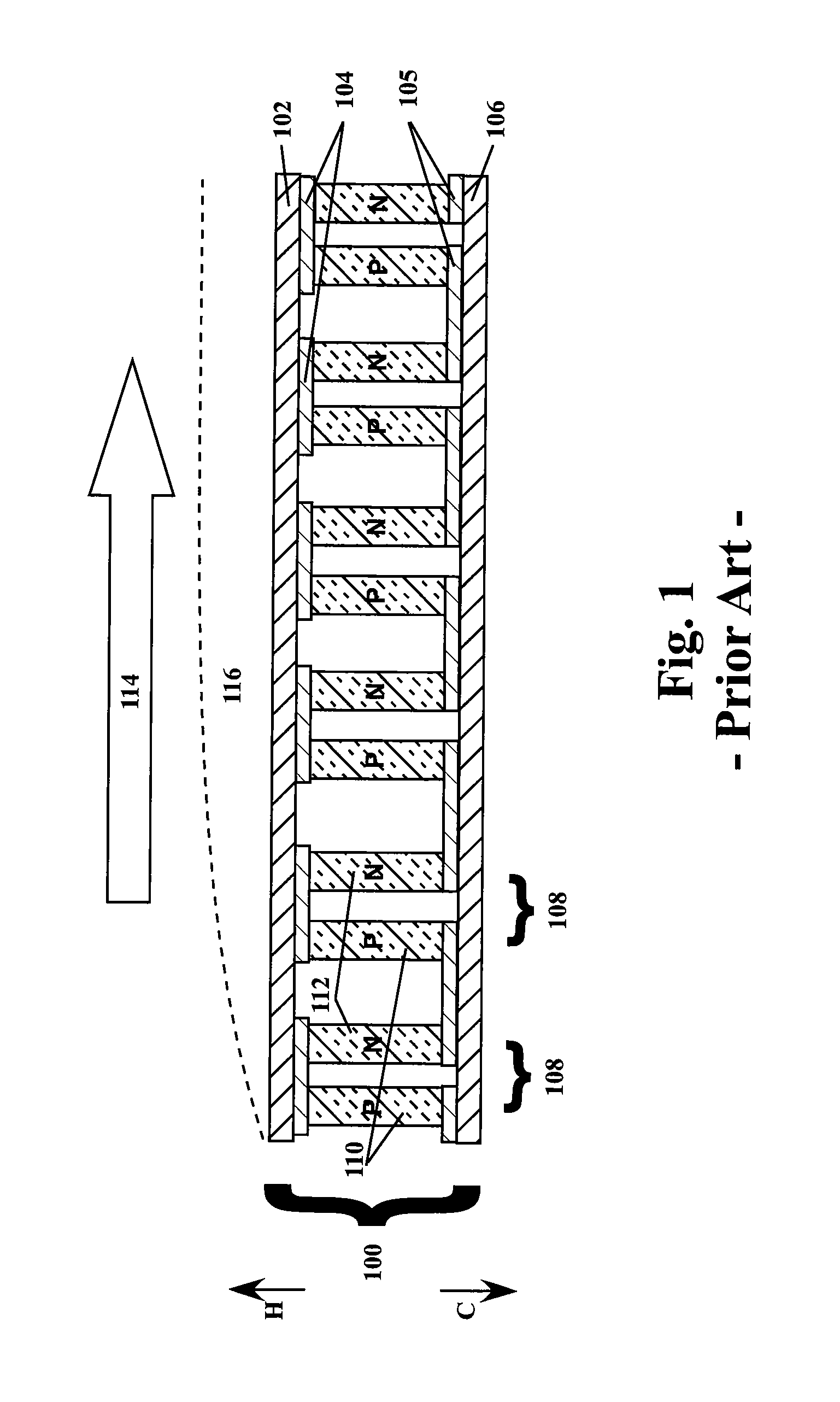
[0033]FIG. 1 shows an example of a prior art electricity generator using the thermoelectric effect. The thermoelectric (TE) generator 100 could be composed of a heat exchanger 102 near the thermal source 114 (at the “hot end”150), another heat exchanger 106 located away from the thermal source 114 (at the “cold end”160), and thermoelectric pairs 108 located between the heat exchangers 102,106. The thermoelectric pairs 108 are composed of a P-type TE element 110 and an N-type TE element 112 each extending from a connection to the “hot end” heat exchanger 102 ...


PUM


Abstract

A system and method for generating electrical power from a heat source utilizing both photonic and thermal conversion are disclosed. Specifically, power is generated by coupling photon converters to thermoelectric pairs in a way such that the thermoelectric pairs gain not only the charge carriers (holes and electrons) generated by the photons absorbed by the photon converters, but also the charge carriers generated by excess heat in the photon converters and an added thermal gradient generated by excess energy in the absorbed photons. Heat exchanger variations for such a system are also disclosed. Specifically, heat exchangers with and without photon emitters are disclosed and variants of refractive indices for heat exchanger systems are disclosed.

Description

CROSS REFERENCE TO RELATED APPLICATIONS[0001]This application claims benefit to U.S. provisional application 60 / 974,400 filed on Sep. 21, 2007, for “Photon Enhanced Thermoelectric Power Generation” by Daniel Yap, et al., the disclosure of which is incorporated herein by reference.BACKGROUND[0002]1. Field[0003]This disclosure relates to the field of deriving electrical power from a heat source. More specifically, this disclosure relates to extracting both thermal and photonic energy from a heat source, especially from a thermal flow.[0004]2. Description of the Related Art[0005]A common thermoelectric (TE) generator is illustrated in FIG. 1. TE generators convert heat into electric current or voltage. Holes and electrons are produced in the P-type and the N-type TE elements, respectively, as a result of thermal excitation and, preferably, doping of the constituent materials. The TE elements have one end (the hot end) contacting a heat exchanger that is at a high temperature and have a...

Claims


Application Information

Patent Timeline
IPC IPC(8): H01L35/30
CPCH02S10/10H01L35/30Y02E10/50H10N10/13
Inventor YAP, DANIELSUMIDA, DAVID S.
Owner HRL LAB
Why Eureka
Try Eureka