Electrical machine

Inactive Publication Date: 2012-10-09
SIEMENS AG
View PDF30 Cites 15 Cited by
  • Summary
  • Abstract
  • Description
  • Claims
  • Application Information

AI Technical Summary

Benefits of technology

[0005]The object of the present invention is to specify a simplified electric machine and a primary part for such an electric machine, as a result of which it can be constructed in a simplified and more cost-effectiv

Problems solved by technology

The design of such an electric machine is very complex since both the primary

Method used


Image

  • Electrical machine
  • Electrical machine
  • Electrical machine

Examples


Embodiment Construction

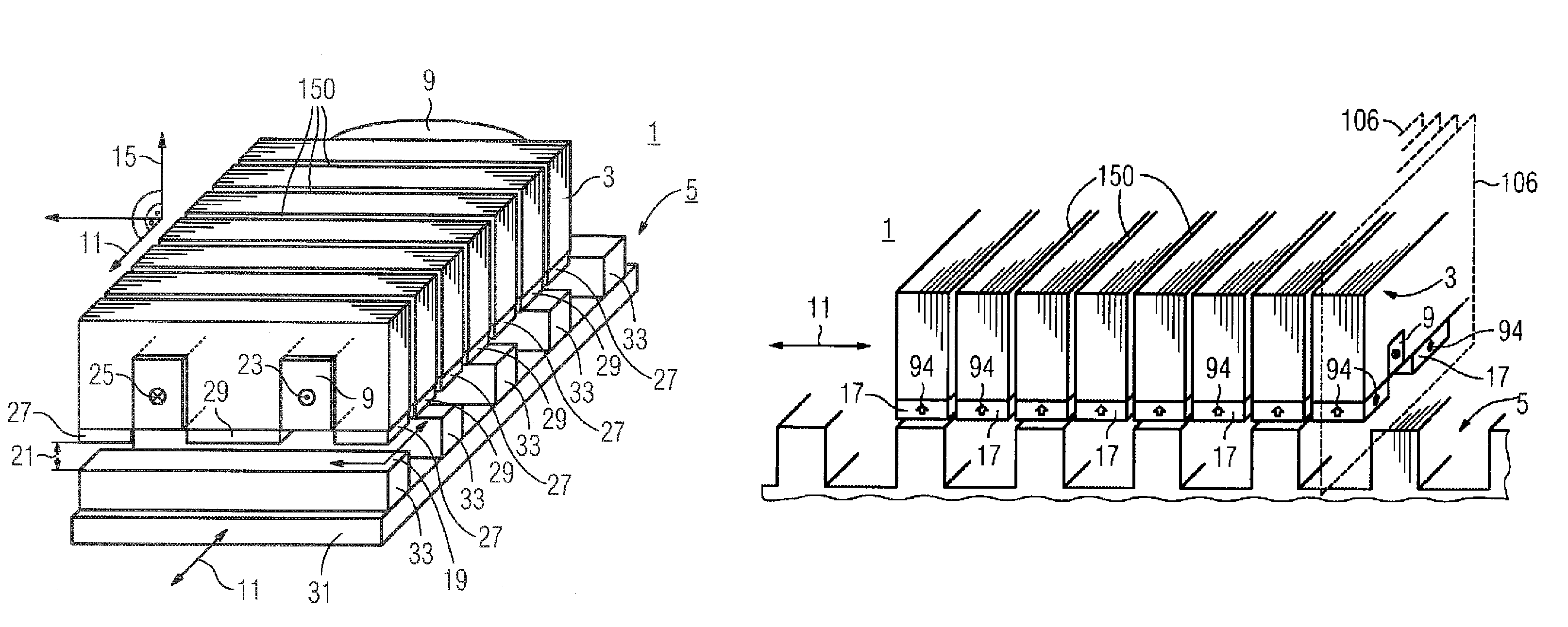
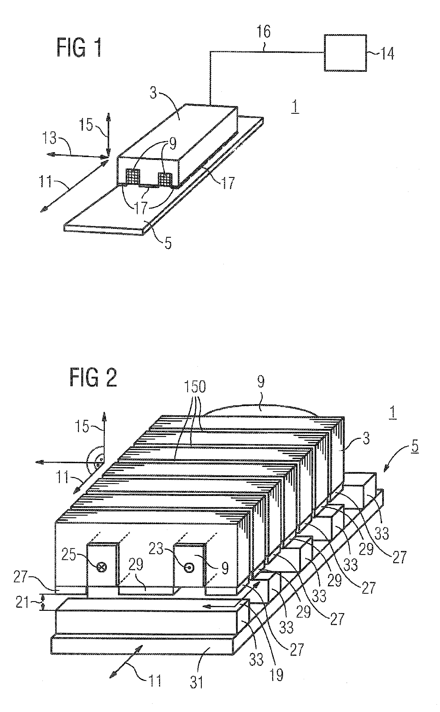
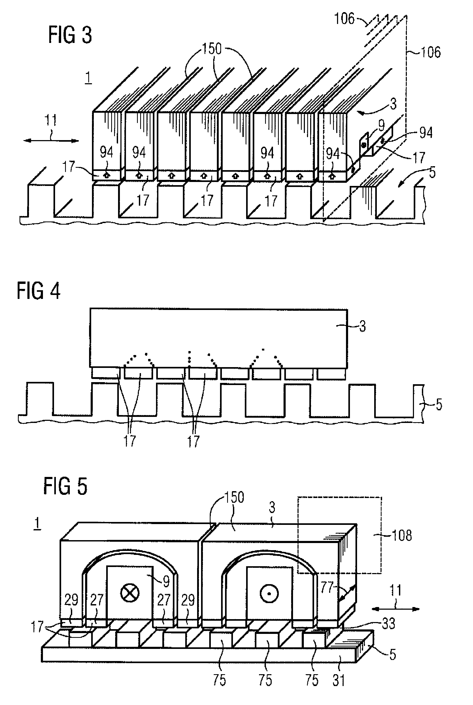
[0063]The illustration in FIG. 1 shows an electric machine 1. The electric machine 1 has a primary part 3 and a secondary part 5. The primary part 3 has a winding 9 and permanent magnets 17. The movement direction of the primary part 3 is identified by means of a double arrow, which runs in the longitudinal direction 11. A further double arrow indicates the transverse direction 13. The normal 15 is determined by means of a third double arrow, the normal being based on an air gap plane 19, the air gap plane 19 not being illustrated in FIG. 1. The air gap plane 19 is illustrated in FIG. 2, however. The electric machine 1 is a linear motor which can be driven by means of a power converter 14, which is connected via a connection cable 16.

[0064]The illustration in FIG. 2 shows an electric machine 1. The primary part 3 is in the form of a laminate stack, the primary part 3 having a winding 9. The winding 9 is a phase winding, it being possible for an alternating current to be applied to t...


PUM


Abstract

The invention relates to an electrical machine (1, 110), which is in particular a synchronous machine, which has a primary part (3, 130) and a secondary part (5, 120), wherein the primary part (3, 130) has a) a first means (9) for producing a first magnetic field and b) a further means (17, 27, 29) for producing a further magnetic field, which in particular is an exciter field, and wherein the first means (9) has at least one winding, and the further means (17, 27, 29) is arranged in the region of an active air gap (21) of the electrical machine between the primary part and the secondary part and has magnetic poles, each having at least one permanent magnet (17).

Description

BACKGROUND OF THE INVENTION[0001]The invention relates to an electric machine and to a primary part of an electric machine.[0002]Electric machines have a primary part and a secondary part. The primary part is in particular opposite the secondary part. The primary part is intended to be supplied with electrical current. The secondary part has, for example, permanent magnets or windings which can be supplied with current. The windings which can be supplied with current, in the case of a synchronous machine, can be supplied with current for example by means of a power converter or, in the case of an asynchronous machine, are supplied with current by induction.[0003]In such electric machines, both the primary part and the secondary part consequently have active magnetic means, which can be used to generate a magnetic field. Active magnetic means are, for example, a winding which can be supplied with current, permanent magnets or a winding in which an electrical current flow can be broug...

Claims


Application Information

Patent Timeline
IPC IPC(8): H02K41/02
CPCH02K21/44H02K41/033H02K1/20H02K1/32
Inventor VOLLMER, ROLF
Owner SIEMENS AG
Why Eureka
Try Eureka