Positionally sequenced loudspeaker system

a position sequence and loudspeaker technology, applied in the direction of transducer details, electrical transducers, coils, etc., can solve the problems of reducing speaker strength, reducing the efficiency of speaker and its ability to produce acoustic output, and overheating of voice coils, so as to increase the overall operating efficiency of the driver and increase the speaker strength

Inactive Publication Date: 2012-10-09
INDUCTION SPEAKER TECH
View PDF42 Cites 148 Cited by
  • Summary
  • Abstract
  • Description
  • Claims
  • Application Information

AI Technical Summary

Benefits of technology

[0018]In some embodiments, the radial component of the magnetic flux density field produced by a magnet assembly may not form a perfect sine wave along the axis of the magnet structure. In some embodiments it may be desirable for the radial component of the flux density field to form a more perfect sine wave. There may also be a need to minimizing cogging (small variations in strength within the range of movement of a cone or traveling assembly. It may also be desirable for the radial magnetic field distribution to have exaggerated peaks, perhaps coincident with pole pieces, so that the speaker strength can be increased within a small range of motion. This can increase the overall operating efficiency of the driver, which may experience infrequent large excursion peaks. Also embodiments can address instances in which the magnetic field may have non-uniform variations due to manufacturing tolerances in the magnetic components.
[0044]Providing a voice coil assembly that allows the convenient use of pre-formed coils during assembly.

Problems solved by technology

This means that at low frequency the volume of air that must be moved to obtain a given SPL is very large when compared to the volume of air that must be moved to obtain the same SPL at high frequency.
An added challenge exists when designing drivers with small piston diameters in that the area is proportional to the square of the diameter, meaning that the piston movement length must go up with the inverse square of the piston diameter to obtain a given SPL.
This reduced speaker strength decreases the efficiency of the speaker and its ability to produce acoustic output.
A large current will tend to increase heat and could even overheat the voice coil 110.
The larger magnet 104 usually increases the weight and cost of the speaker, which is a commercial disadvantage.
This reduction in flux can have the negative effect of reduced speaker strength.
This can be a disadvantage in terms of weight and portability among other aspects.
The low-frequency performance of a conventional driver utilized in a tuned-resonance enclosure can often be limited by excursion limits 112 of the driver.
Even though the driver can produce a moderate excursion with a moderate amount of magnetic leakage 103, the magnetic leakage usually reduces the overall efficiency of the driver and can limit even the mid-frequency and high-frequency performance of the driver, which do not benefit from the resonant enclosure.
This can produce an audible time delay between the low-frequency and high-frequency components of the signal, and can represent a kind of unwanted distortion.
Another more common failure mode of loudspeakers can include thermal overloading of voice coil 110, which can occur when the loudspeaker is operated at high volume for extended durations.
Due to the random nature of audio signals, the user has no way of knowing if and when these conditions will exist, so the speaker system must generally be operated in a conservative fashion.
Sometimes, operating the speaker in a conservative fashion causes the speaker to be larger and heavier than would otherwise be required in a given application.
There is also a distortion phenomenon in many ordinary loudspeakers due to the fact that the field induced by the current in the coil may add to and / or subtract from the field created by the permanent magnet.
This may also be a source of audio distortion.
Another problem with a conventional loudspeaker driver is that the speaker strength can change with voice coil 110 position.
This can cause nonlinear distortion in the acoustic output.
This nonlinear distortion can even represent the largest source of distortion in the entire sound reproduction system.
In fact, nonlinear distortion created in this manner is frequently fifty times the total distortion produced by the remaining components in the signal chain combined.
Non-constant speaker strength can also cause distortion.
There can exist a design tradeoff between the efficiency of the speaker and the distortion created by the non-constant speaker strength function.
This can reduce the efficiency of the speaker, since the resistive losses are often increased and the increased mass may result in decreases in sound pressure output for a given current through the voice coil.

Method used


Image

  • Positionally sequenced loudspeaker system
  • Positionally sequenced loudspeaker system
  • Positionally sequenced loudspeaker system

Examples


Embodiment Construction

[0091]As mentioned earlier, the present invention includes a variety of aspects, which may be combined in different ways. The following descriptions are provided to list elements and describe some of the embodiments of the present invention. These elements are listed with initial embodiments, however it should be understood that they may be combined in any manner and in any number to create additional embodiments. The variously described examples and embodiments should not be construed to limit the present invention to only the explicitly described systems, techniques, and applications. Further, this description should be understood to support and encompass descriptions and claims of all the various embodiments, systems, techniques, methods, devices, and applications with any number of the disclosed elements, with each element alone, and also with any and all various permutations and combinations of all elements in this or any subsequent application.

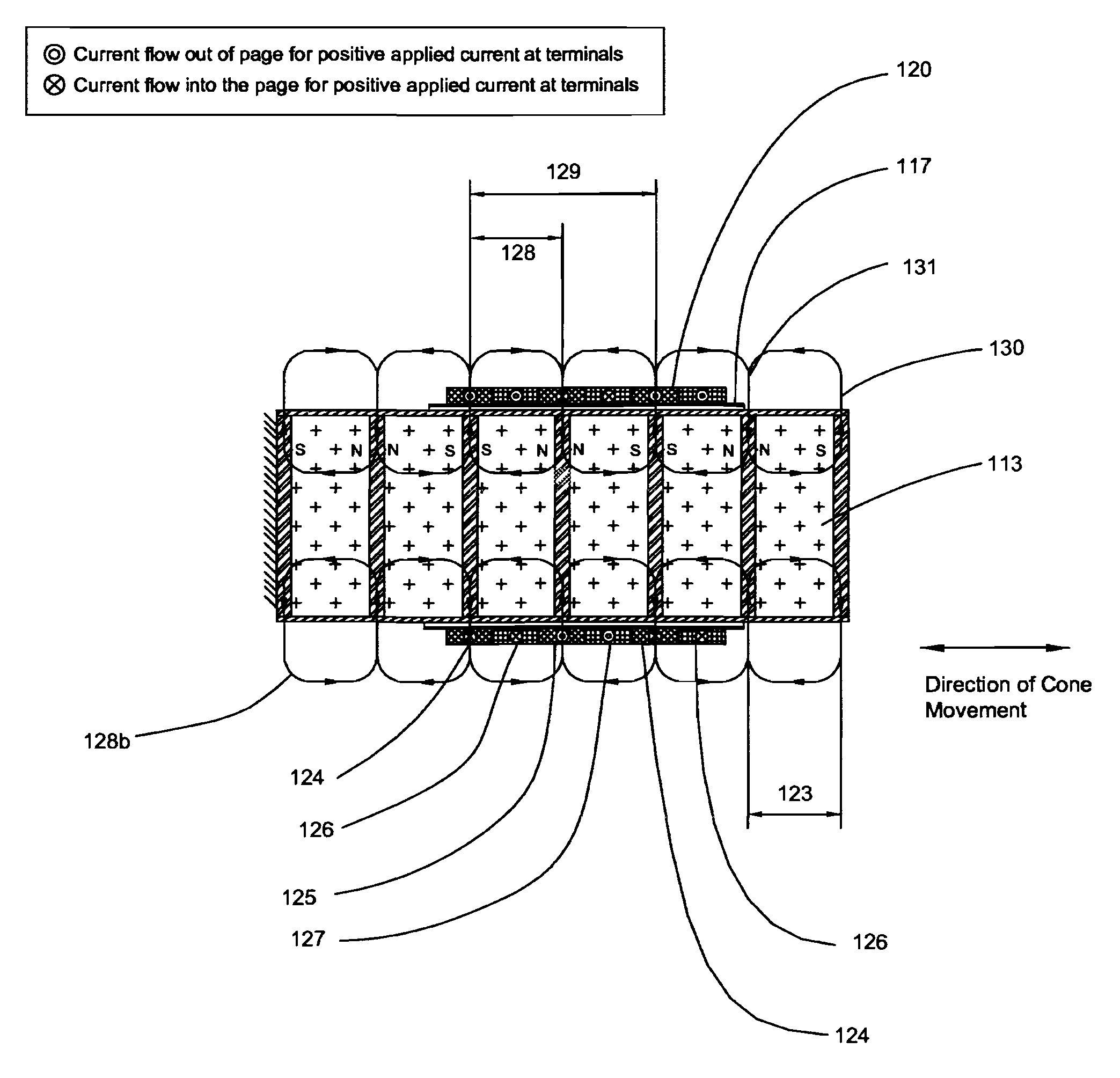
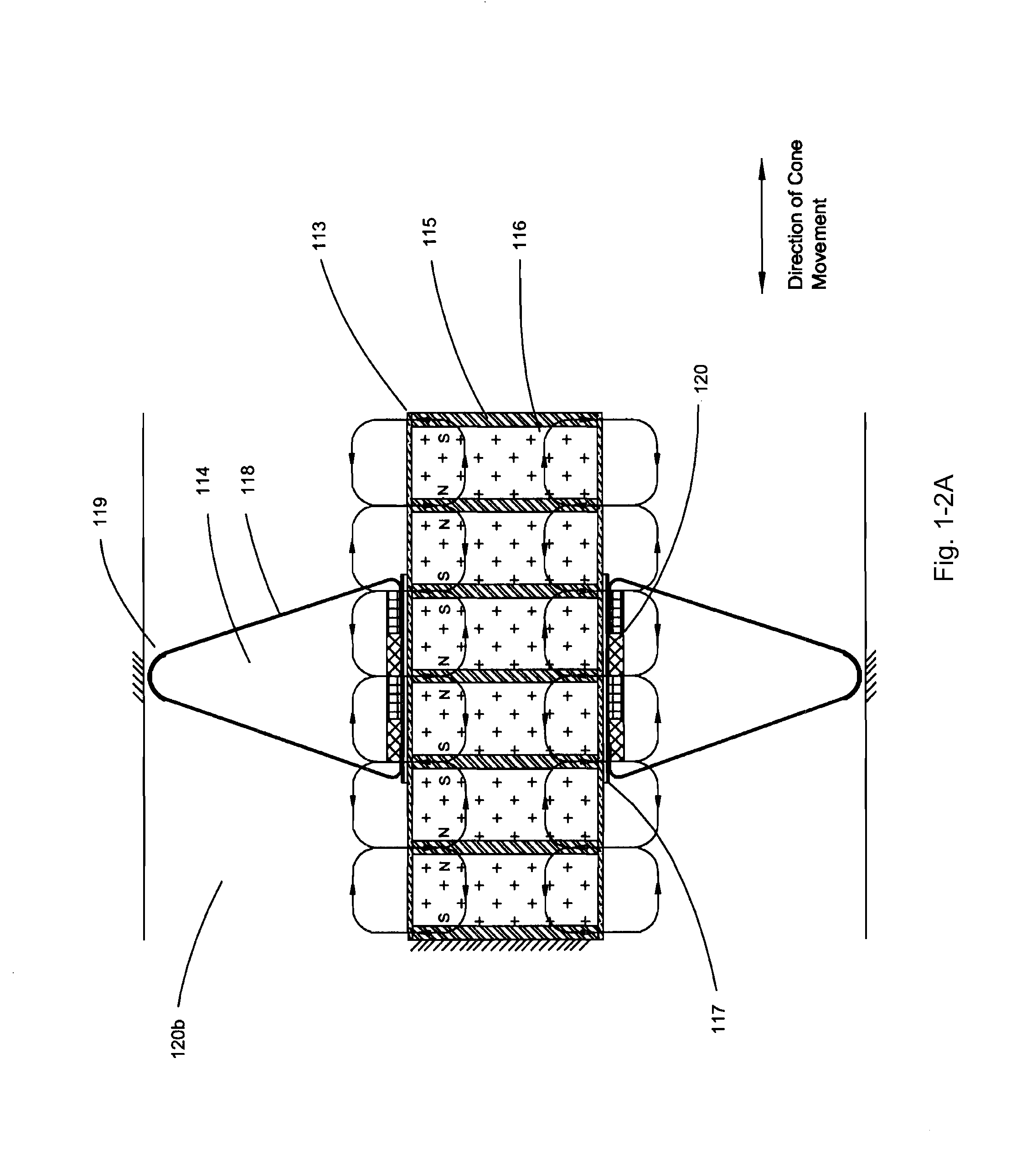
[0092]FIG. 1-2A shows a cross-sec...


PUM


Abstract

A variety of loudspeaker arrangements may have any of multiple adjacent magnetic circuits, single magnetic circuits, an improved loudspeaker voice coil assembly, multiple voice coil windings (124-127, 315-317), and commutated current. The radial direction of flux may alternate at adjacent poles and may have a controller that commands the current through each of the windings. The position of the moving components may be measured or inferred by the controller (213). An encoding track (318a) applied to the surface of the assembly may allow the assembly to function as part of a position transducer to permit appropriate action based on position. Calculated or sensed actual position may be used to determine the relative current in each of the windings and the controller may have compensation such as a motion control algorithm, thermal monitoring, and management of the driver. The voice coil assembly (305c) may have foil conductors applied to a substrate to connect and interconnect a single or multiple voice coil windings with minimal effect on the magnetic gap (303b) width.

Description

[0001]This application is the United States National Stage of international application number PCT / US07 / 63416, filed Mar. 6, 2007 which claims the benefit of U.S. Provisional Application No. 60 / 779,846 filed 6 Mar. 2006, U.S. Provisional Application No. 60 / 845,930 filed 19 Sep. 2006, and U.S. Provisional Application No. 60 / 900,399 filed 9 Feb. 2007, hereby incorporated by reference herein.TECHNICAL FIELD[0002]This invention relates to loudspeaker design and loudspeaker drivers that produce more sound and produce less distortion and offer less heat generation. Specifically it involves the technical fields of loudspeaker drivers that are intended to produce high acoustic output by utilizing a large cone excursion, voice coil formers used in loudspeaker drivers, and voice coils that have multiple coils or position sensing. Embodiments of the present invention include loudspeaker systems having multiple magnetic circuits, multiple voice coil windings, and current sequencing among coils ...

Claims


Application Information

Patent Timeline
Patent Type & Authority Patents(United States)
IPC IPC(8): H04R25/00
CPCH04R9/025H01F5/04H04R7/12H04R9/046H04R2209/041
Inventor BAILEY, ADAM H.
Owner INDUCTION SPEAKER TECH
Why Eureka
Try Eureka