
Assembled battery charging method and battery charging system

a battery charging and battery charging technology, applied in the direction of battery arrangement, transportation and packaging, electrical generators, etc., can solve the problems of increasing the voltage of commercial power supplies, increasing the reactive resistance, and the valve-regulated type is more susceptible to internal resistance variation, so as to reduce the degree of stratification, the charging current value is reduced, and the charging time is longer.

Active Publication Date: 2012-10-16
GS YUASA INT LTD
View PDF28 Cites 19 Cited by
  • Summary
  • Abstract
  • Description
  • Claims
  • Application Information

AI Technical Summary

Benefits of technology

The present invention proposes an assembled battery charging system and method that reduces decreases in battery capacity when repeatedly charging valve-regulated lead-acid batteries. The charging system includes multiple charging units that charge the secondary batteries in parallel using valve-regulated lead-acid batteries. Each charging unit executes multistage constant-current charging, which involves supplying current of a prescribed set current value to each secondary battery until its terminal voltage reaches a prescribed charging cutoff voltage. The set current value is reduced each time constant-current charging is repeated. This method helps to maintain the battery's capacity and reduces the risk of decreases in battery capacity attributable to strification.

Problems solved by technology

When considering charging the batteries using the configurations described above, the former configuration is only able to use charging apparatuses having high-voltage specifications for charging, and results in problems such as having to increase the voltage of commercial power supplies.
On the other hand, since reactive resistance, which has a greater effect than component resistance, is inversely proportional to electrolyte volume, valve-regulated lead-acid batteries, in which electrolyte volume is lower than that of fluid-type lead-acid batteries, are susceptible to increases in reactive resistance.
Consequently, valve-regulated types are more susceptible to variations in internal resistance (component resistance+reactive resistance).
Consequently, valve-regulated lead-acid batteries are less suitable for charging in parallel as compared with fluid-type lead-acid batteries.

Method used


Image

  • Assembled battery charging method and battery charging system
  • Assembled battery charging method and battery charging system
  • Assembled battery charging method and battery charging system

Examples


first embodiment

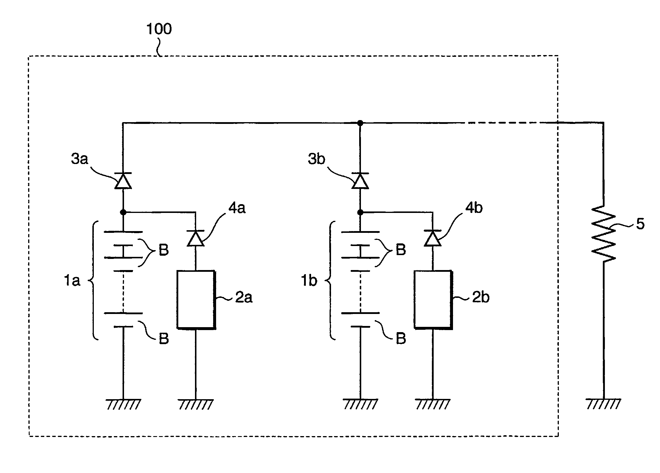
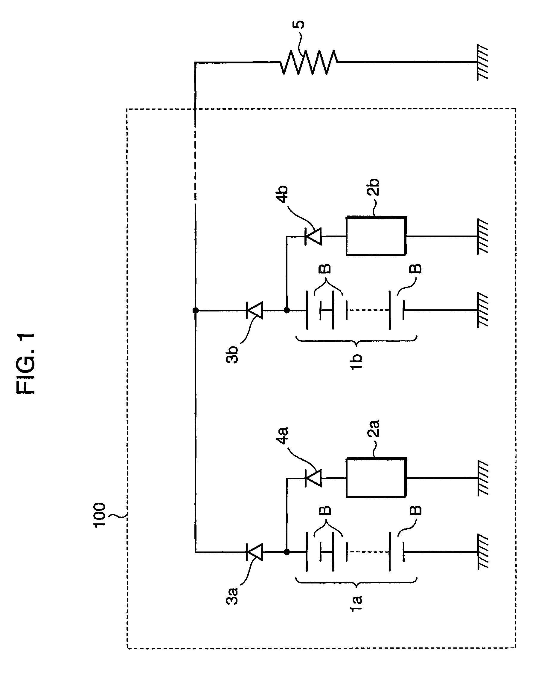
[0063]The assembled battery charging method and battery charging system according to a first embodiment of the present invention use an assembled battery charging method in which, for example, series circuits (secondary batteries), in which a plurality of valve-regulated lead-acid batteries are connected in series, are connected in parallel to a load. In this charging method, charging apparatuses are respectively connected to each series circuit, each charging apparatus detects the charging voltage of each series circuit, and n-stage constant-current charging is carried out in which constant-current charging is repeated a plurality of times by changing the current value n−1 times (where n is an integer of 2 or more).

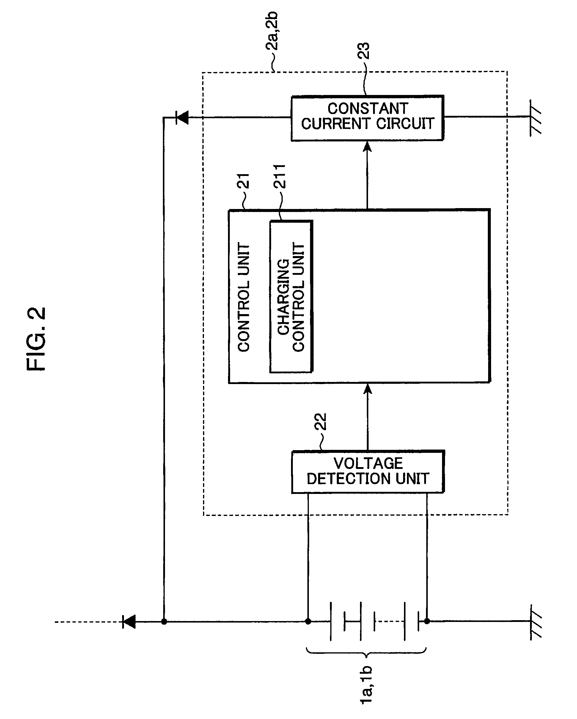
[0064]FIG. 1 is a block diagram representing a first embodiment of a battery charging system to which the assembled battery charging method according to the present invention is applied. A battery charging system 100 shown in FIG. 1 is provided with secondary batteries 1...

second embodiment

[0091]An assembled battery charging method and battery charging system according to a second embodiment of the present invention sustains the final constant-current charging Cn for a prescribed supplemental charging time tn regardless of the terminal voltage V of a secondary battery.

[0092]During n-stage constant-current charging in which a current value is changed n times, since the nth constant current of the final nth stage of charging is frequently set to an extremely small value, changes in the voltage V of the secondary battery versus time are also extremely small. Consequently, there is increased susceptibility to the effects of noise in the vicinity of the charging cutoff voltage Ven, resulting in increased likelihood of error when determining the charging cutoff voltage according to voltage (determination of charging cutoff voltage by a comparison between the charging cutoff voltage Ven and the voltage V in Step S06 of FIG. 5). Therefore, by ending the finally executed const...

third embodiment

[0103]An assembled battery charging method and battery charging system according to a third embodiment of the present invention is an assembled battery charging method in which, for example, series circuits (secondary batteries), in which a plurality of valve-regulated lead-acid batteries are connected in series, are connected in parallel to a load, wherein charging apparatuses are respectively connected to each series circuit, each charging apparatus detects the charging voltage of each series circuit, and in carrying out n-stage constant-current charging in which constant-current charging is repeated a plurality of times by changing the current value n−1 times (where n is an integer of 2 or more), the amount of electricity charged in each series circuit is changed based on the thermal history of each series circuit.

[0104]According to this configuration, in consideration of the thermal history through which each series circuit has gone through (for example, the manner in which the ...


PUM


Abstract

The present invention provides a battery charging system that includes: an assembled battery, in which a plurality of secondary batteries are connected in parallel using valve-regulated lead-acid batteries in which separators impregnated with electrolyte are arranged between mutually opposed plate-like positive electrodes and negative electrodes; and a plurality of charging units that are provided corresponding to the respective secondary batteries and that charge the corresponding secondary battery, respectively, wherein each of the charging units executes multistage constant-current charging in which constant-current charging is repeated a preset plurality of times for supplying current of a prescribed set current value to each corresponding secondary battery until the terminal voltage of the each corresponding secondary battery reaches a prescribed charging cutoff voltage, and also the set current value is reduced each time the constant-current charging is repeated.

Description

RELATED APPLICATIONS[0001]This application is the U.S. National Phase under 35 U.S.C. §371 of International Application No. PCT / JP2009 / 007121, filed on Dec. 22, 2009, which in turn claims the benefit of Japanese Application No. 2009-001280, filed on Jan. 7, 2009, Japanese Application No. 2009-248724, filed on Oct. 29, 2009 and Japanese Application No. 2009-248725, filed on Oct. 29, 2009, the disclosures of which Applications are incorporated by reference herein.TECHNICAL FIELD[0002]The present invention relates to a method for charging an assembled battery composed of valve-regulated lead-acid batteries, and to a battery charging system for charging this type of assembled battery.BACKGROUND ART[0003]Amidst growing trends toward reducing carbon dioxide emissions and depletion of petroleum resources, there is a pressing need for the development of compact vehicles that use only lead-acid batteries and other secondary batteries as motive power sources. In particular, since lead-acid ba...

Claims


Application Information

Patent Timeline
Patent Type & Authority Patents(United States)
IPC IPC(8): H02J7/00
CPCB60W10/26H01M10/121H01M10/441H02J7/0018H02J7/0073H02J7/008Y02E60/126H02J7/0071Y02E60/10H02J7/007182
Inventor JIMBO, HIROYUKIMUROCHI, HARUMIKIKUCHI, TOMOYAYOSHIHARA, YASUYUKI
Owner GS YUASA INT LTD
Learn More