Tinted semi-finished lens having impact resistance and method for manufacturing the same
a semi-finished, lens technology, applied in the field of semi-finished lenses, can solve the problems of deformation and distortion difficulty in adhesion between the two layers, and variation in the effects of the opposing layer, so as to achieve the effect of reducing the tendency, reducing the power of the lens, and being easily broken
- Summary
- Abstract
- Description
- Claims
- Application Information
AI Technical Summary
Benefits of technology
Problems solved by technology
Method used
Image
Examples
example 1
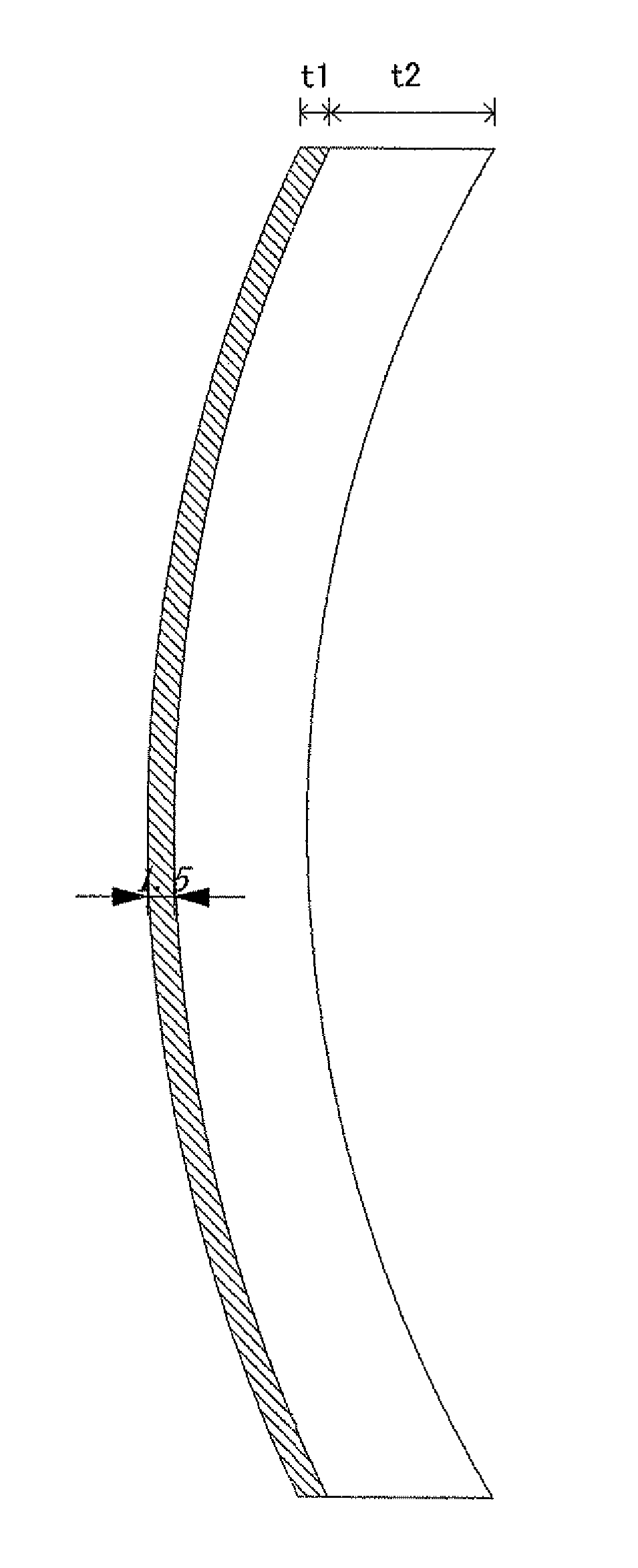
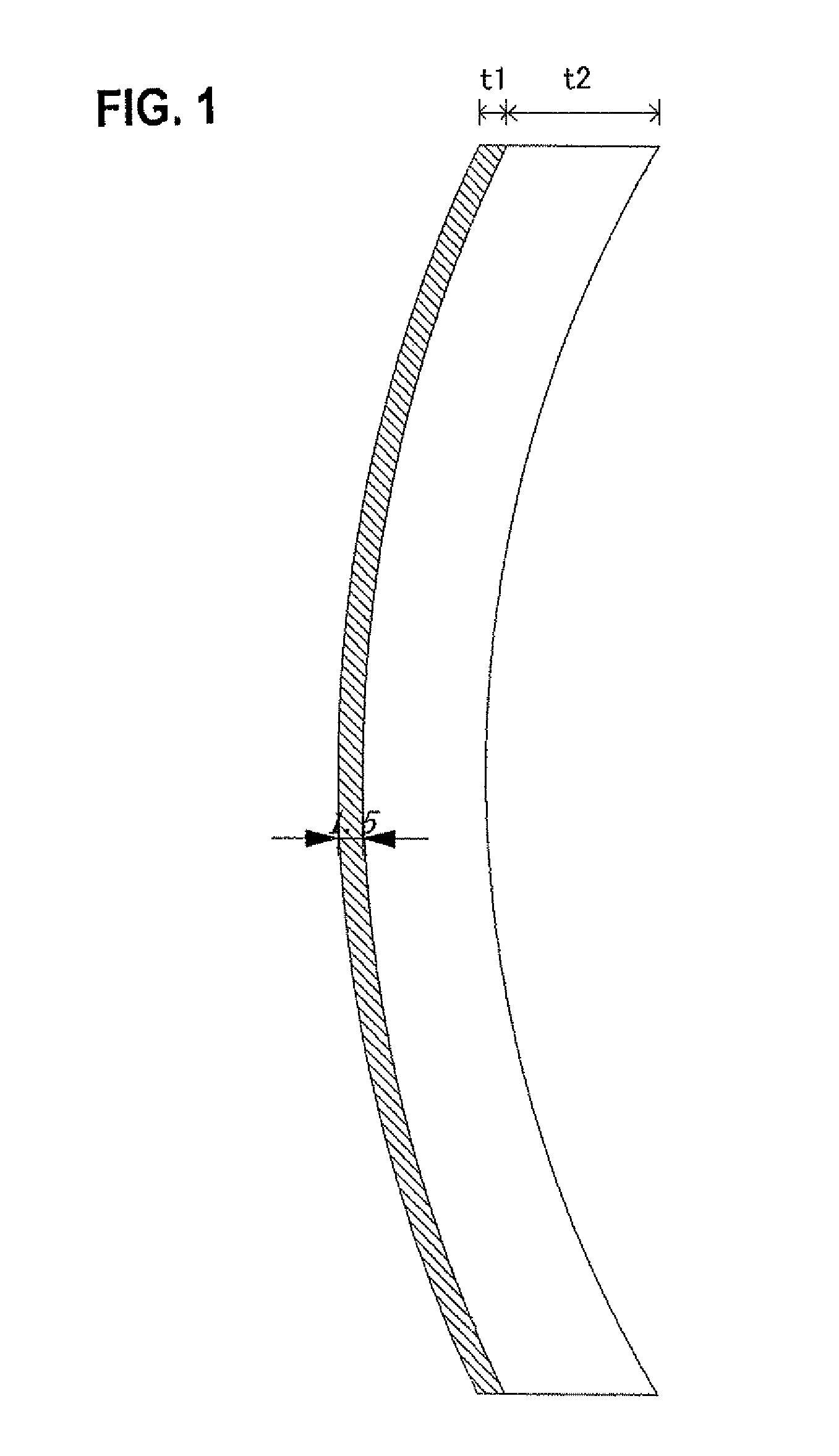
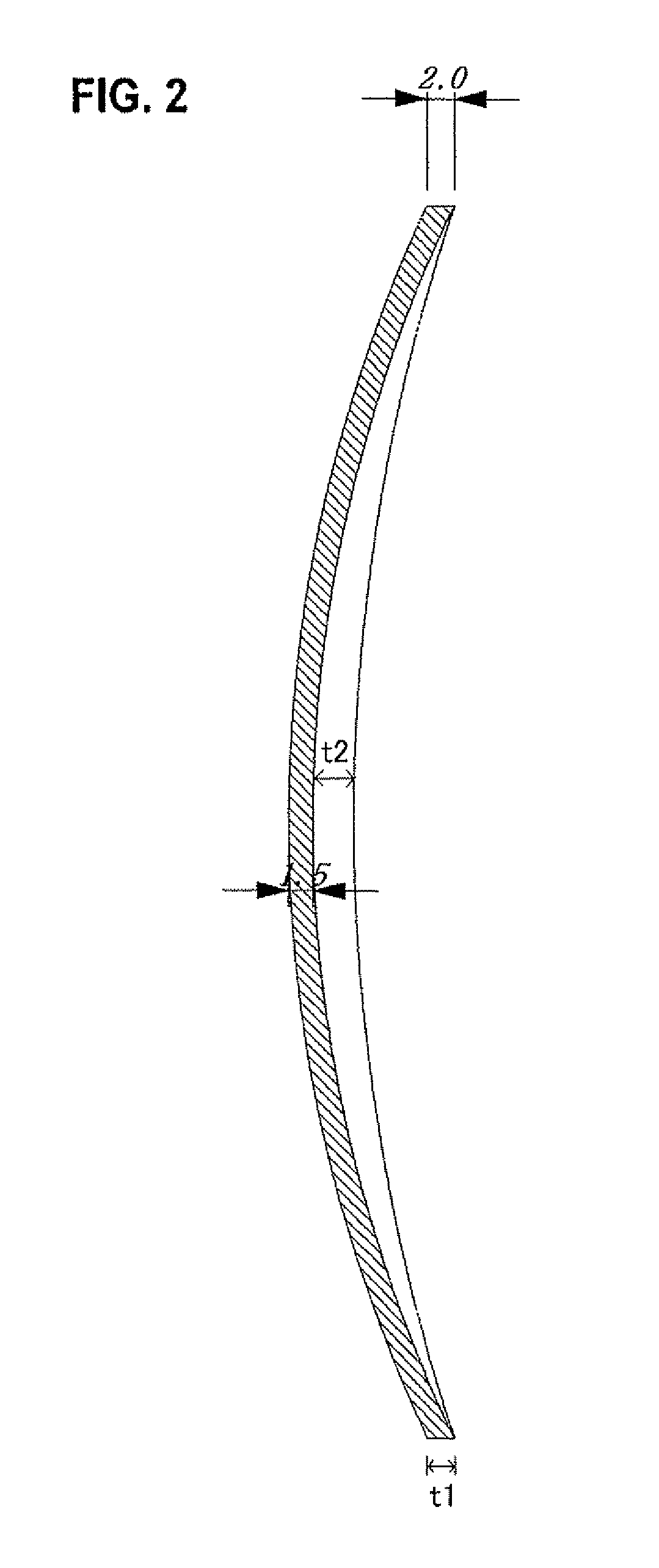
[0037]Example 1 of the invention will be described with reference to FIG. 1 and FIG. 2.
[0038]Polycarbonate (a molecular weight of 17,000) colored with black ink color having a transmission factor of 25% when the front curve was 8R (a curvature radius of 66.25 mm), the back curve was 8.2R (a curvature radius of 64.75 mm), and the center thickness was 1.5 mm was molded at a resin temperature of 300° C. with a mold at 110° C. to give a tinted molded product having a thickness of 1.5 mm and little distortion.
[0039]The obtained molded product was inserted into a concave mold, and to the back side a transparent polycarbonate (a molecular weight of 22,000) layer having a thickness of 8 mm was formed to give a semi-finished lens shown in FIG. 1.
[0040]The semi-finished lens obtained in this manner was cut and polished to make a plus power lens having a center thickness of 4.6 mm and a curvature radius of the back curve of 105 mm (5.04R), and then the lens periphery was processed to make a le...
example 2
[0042]The drop ball test according to ANSI (American National Standard Institute) was performed on the obtained lens (an iron ball with a weight of 7 oz was dropped from a height of 50.0 in. to examine fragment scattering due to lens cracking). As a result, the fragment scattering was not observed to prove the impact resistance. In contrast, when the drop ball test was performed on the tinted layer having a thickness of 1.5 mm alone, the fragments were scattered.
[0043]Example 2 of the present invention will be described with reference to FIG. 1, FIG. 3, and FIG. 7. The efficient method for manufacturing two molded products when two sets of cavity and core molds were prepared for molding will be described in detail in Example 3 with reference to FIG. 8.
[0044]Polycarbonate (a molecular weight of 17,000) colored with black ink color having a transmission factor of 25% when the front curve was 8R (a curvature radius of 66.25 mm), the back curve was 8R (a curvature radius of 64.75 mm), a...
example 3
[0049]Example 3 of the present invention will be described with reference to FIG. 8.
[0050]The method can efficiently provide a lens that has the least distortion and deformation. The method employing two sets of cavity and core molds will be described. The following processes 1) to 6) correspond to the processes in the drawing.
[0051]1) Two sets of cavity and core molds for molding were prepared. Each core mold had the same shape in the lens molding part (corresponding to the back face of the lens). The second cavity mold has a larger sprue-runner (1) for pouring resin than the first cavity mold to keep the flow pass for a colored resin. In addition, the second cavity mold had the lens molding part (corresponding to the front face of the lens) that has the same curve as in the first cavity mold and is placed 1.5 mm backward comparing with that in the first cavity mold. (In Fig., the broken lines (2) show the larger part than the first cavity mold)
[0052]2) to 3) The core mold and the ...
PUM
 Abstract
Description
Claims
Application Information
 - R&D
- Intellectual Property
- Life Sciences
- Materials
- Tech Scout
- Unparalleled Data Quality
- Higher Quality Content
- 60% Fewer Hallucinations
Browse by: Latest US Patents, China's latest patents, Technical Efficacy Thesaurus, Application Domain, Technology Topic, Popular Technical Reports.
© 2025 PatSnap. All rights reserved.Legal|Privacy policy|Modern Slavery Act Transparency Statement|Sitemap|About US| Contact US: help@patsnap.com


