
Super sensitive UV detector using polymer functionalized nanobelts

a functionalized nanobelt and super sensitive technology, applied in the field of electronic sensors, can solve the problems of limiting the application of zinc oxide nanowire nanosensors for fast uv detection and imaging, and little attention to improving response and recovery tim

Inactive Publication Date: 2012-10-23
GEORGIA TECH RES CORP
View PDF46 Cites 0 Cited by
  • Summary
  • Abstract
  • Description
  • Claims
  • Application Information

AI Technical Summary

Benefits of technology

The solution achieves a significant enhancement in UV response speed, increasing sensitivity by four orders of magnitude and reducing reset time from seconds to milliseconds, enabling fast and selective UV detection at room temperature without the need for cooling.

Problems solved by technology

However, little attention has been paid on improving the response and recovery time especially the reset-time (defined as the time need to recovery to 1 / e (37%) of the maximum photocurrent), which may limit the applications of zinc oxide nanowire nanosensors for fast UV detection and imaging.

Method used


Image

  • Super sensitive UV detector using polymer functionalized nanobelts
  • Super sensitive UV detector using polymer functionalized nanobelts
  • Super sensitive UV detector using polymer functionalized nanobelts

Examples


Embodiment Construction

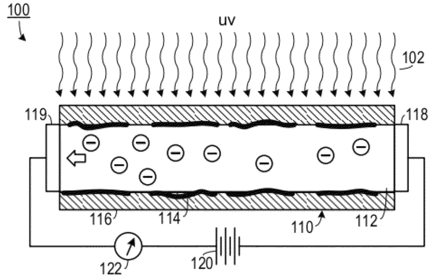
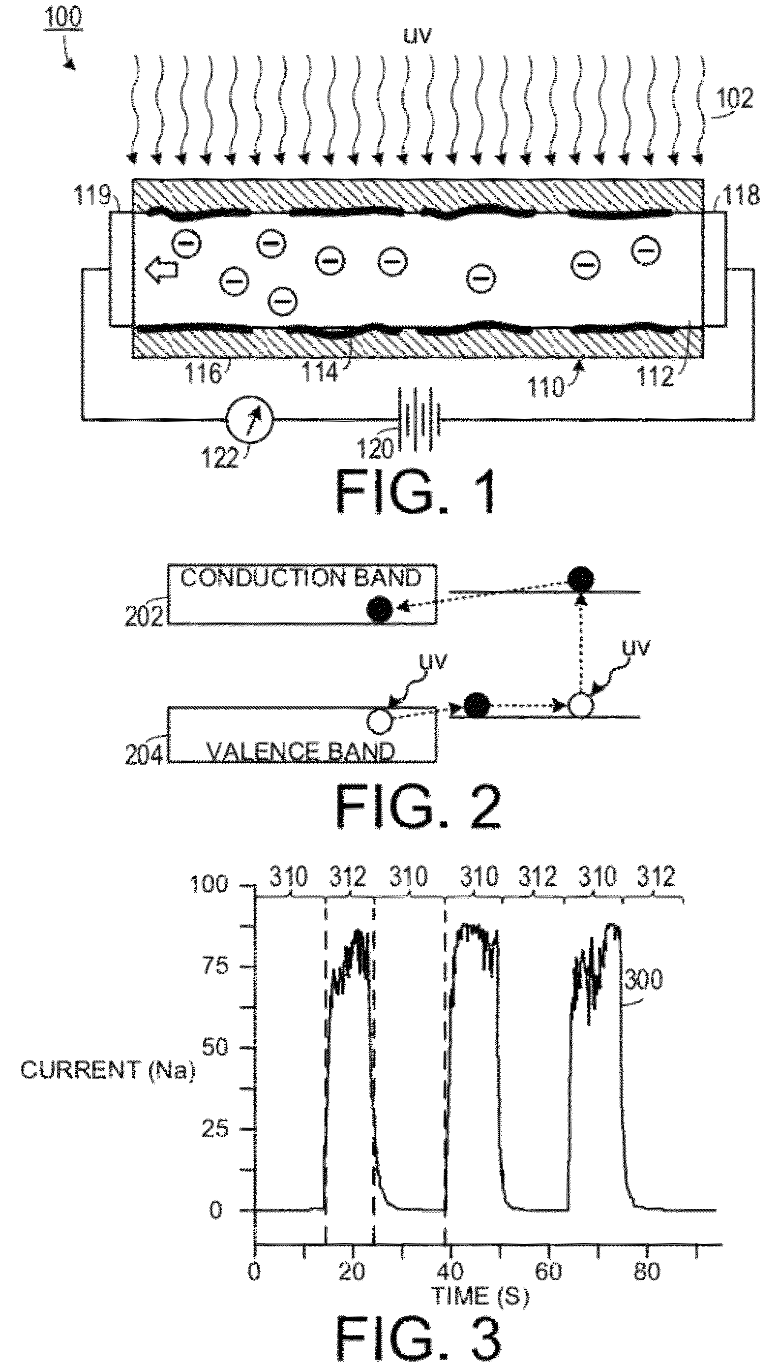
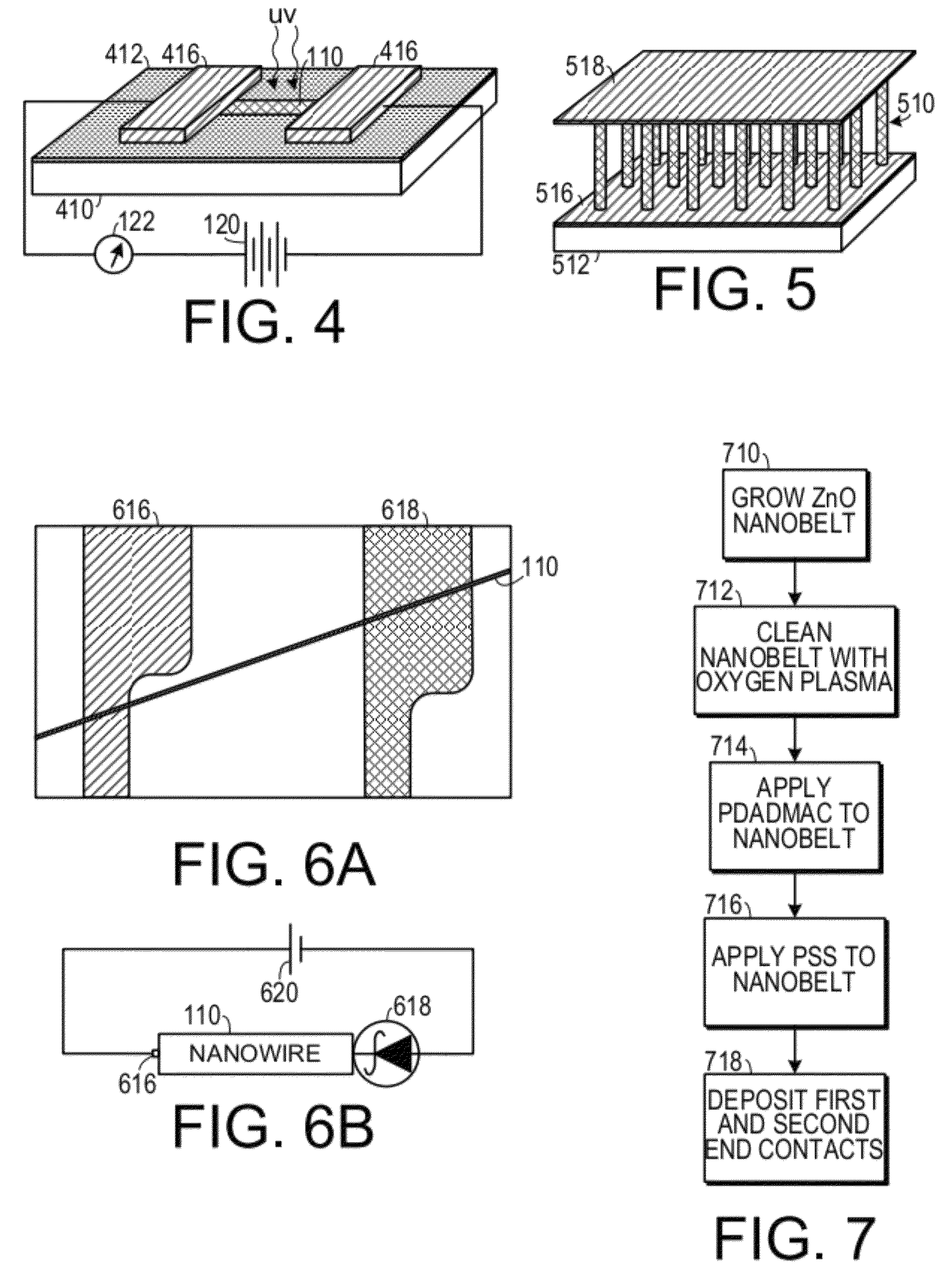
[0020]A preferred embodiment of the invention is now described in detail. Referring to the drawings, like numbers indicate like parts throughout the views. Unless otherwise specifically indicated in the disclosure that follows, the drawings are not necessarily drawn to scale. As used in the description herein and throughout the claims, the following terms take the meanings explicitly associated herein, unless the context clearly dictates otherwise: the meaning of “a,”“an,” and “the” includes plural reference, the meaning of “in” includes “in” and “on.” Also as used herein, “nanobelt” includes elongated nanostructures such as nanowires and nanotubes.

[0021]U.S. Pat. Nos. 6,586,095, 6,918,959 and 7,220,310 and 7,351,607, all issued to Wang et al., disclose methods for making metal oxide nanostructures, the entirety of each of these patents is incorporated herein by reference for the purpose of disclosing methods of generating metal oxide nanostructures.

[0022]As shown in FIG. 1, one emb...


PUM


Abstract

An ultraviolet light sensor includes an elongated metal oxide nanostructure, a layer of an ultraviolet light-absorbing polymer, a current source and a current detector. The elongated metal oxide nanostructure has a first end and an opposite second end. The layer of an ultraviolet light-absorbing polymer is disposed about at least a portion of the metal oxide nanostructure. The current source is configured to provide electrons to the first end of the metal oxide nanostructure. The current detector is configured to detect an amount of current flowing through the metal oxide nanostructure. The amount of current flowing through the metal oxide nanostructure corresponds to an amount of ultraviolet light impinging on the metal oxide nanostructure.

Description

CROSS-REFERENCE TO RELATED APPLICATION(S)[0001]This application claims the benefit of U.S. Provisional Patent Application Ser. No. 61 / 078,607, filed Jul. 7, 2008, and U.S. Provisional Patent Application Ser. No. 61 / 165,191, filed Mar. 31, 2009, the entirety of each of which is hereby incorporated herein by reference.STATEMENT OF GOVERNMENT INTEREST[0002]This invention was made with support from the U.S. government under grant number DE-FG02-07ER46394, awarded by the Department of Energy and grant number W31P4Q06C0262, awarded by the U.S. Army. The Government has certain rights in the invention.FIELD OF THE INVENTION[0003]The present invention relates to electronic sensors and, more specifically, to a sensor for ultra-violet light.DESCRIPTION OF THE PRIOR ART[0004]Ultraviolet (UV) photon detectors have a wide rang of applications from environmental monitoring, missile launching detection, space research, high temperature flame detection to optical communications. For these applicatio...

Claims


Application Information

Patent Timeline
Patent Type & Authority Patents(United States)
IPC IPC(8): H01L35/24H10N10/856
CPCG01J1/429H01L31/03529
Inventor WANG, ZHONG L.LAO, CHANGSHIZHOU, JUN
Owner GEORGIA TECH RES CORP
Learn More