Flame detection method and flame detection device

A technology of flame detection and flame, which is applied in the field of flame detection devices and can solve problems such as complex structures

Inactive Publication Date: 2006-05-31
YAMATAKE HONEYWELL CO LTD
View PDF4 Cites 9 Cited by
  • Summary
  • Abstract
  • Description
  • Claims
  • Application Information

AI Technical Summary

Problems solved by technology

[0004] However, in the ultraviolet detection device shown in the above-mentioned Patent Document 2, for example, Figure 7 (the above patent document 2 Figure 4 ) shows that although the self-luminous spectrum of flame can be detected well, there is a problem that not only must use a variety of ultraviolet detectors made of different materials such as its negative electrode (cathode) and have different detection wavelength regions, but also Its structure is very complex

Method used


Image

  • Flame detection method and flame detection device
  • Flame detection method and flame detection device
  • Flame detection method and flame detection device

Examples


Embodiment Construction

[0021] Hereinafter, a flame detection method and a flame detection device according to an embodiment of the present invention will be described with reference to the drawings.

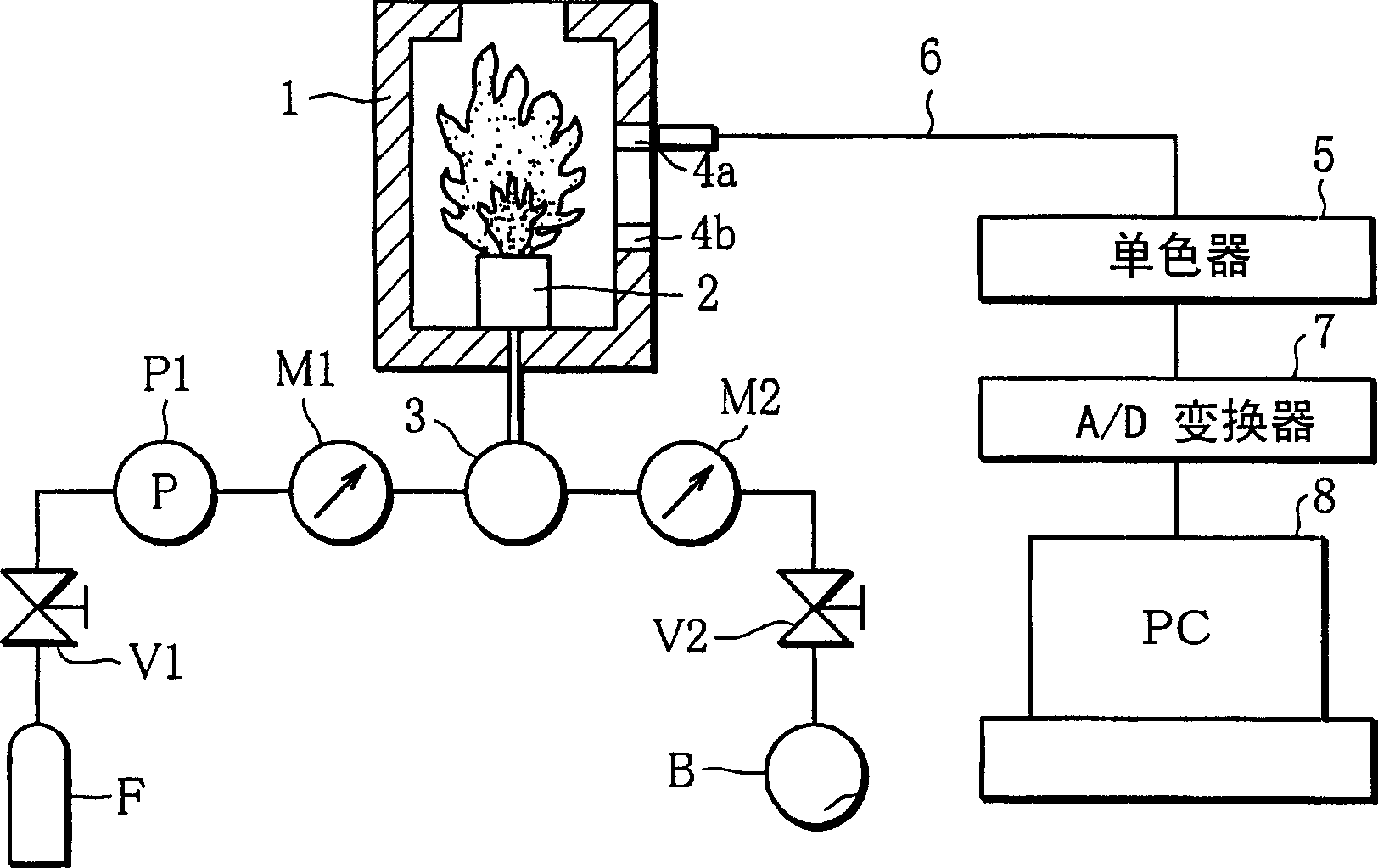
[0022] figure 1 It is a schematic structural diagram showing a lean burn device implementing the method of the present invention and a flame detection device mounted on the lean burn device. 1 is a combustion furnace. This combustion furnace 1 is a rectangular furnace, such as surrounding it with refractory bricks or ceramic fibers, etc., and the internal volume of the combustion furnace is 2.58 × 10 -3 m 3 , the upper part is provided with an exhaust port of 100×100mm, and the heat load of the combustion chamber is set at 1.16×10 3 kW / m 3 . In addition, the burner 2 installed in the combustion furnace 1 is an alcove type with an inner diameter of 40 mm and a height of 60 mm. Fuel (for example, propane gas) and air are mixed and supplied to the burner 2 at an air ratio of, for example, 0.8 to 1....


PUM


Abstract

A flame detection method capable of detecting a flame simply and effectively by using a UV detector having a comparatively small detection wavelength area. A plurality of spontaneously emitted light intensities having the same radical species but different wavelengths are measured respectively out of a spontaneously emitted light spectra of a UV area in the spontaneously emitted light components of a flame to determine emitted light intensity ratios that are mutual ratios between the measured spontaneously emitted light intensities with respective wavelengths, and a flame is detected based on the relations between those emitted light intensity ratios and flame temperatures or the relations between emitted light intensity ratios and air ratios of mixed air used for combustion. Especially, the OH zone spectrum of electron transition A<2>∑<+>->X<2>Pi from an excited state by combustion to a normal sate out of flame spontaneously emitted light components by lean combustion is measured, and emitted light intensity ratios between OH (2,0) in the vicinity of wavelength 260 nm, OH (1,0) in the vicinity of wavelength 280 nm, OH (2,1) in the vicinity of wavelength 287 nm, and OH (0,0) in the vicinity of wavelength 306 nm are determined to detect a flame state.

Description

technical field [0001] The present invention relates to a flame detection method and a flame detection device suitable for detecting the state of a flame formed by combustion, especially a flame formed by lean combustion. Background technique [0002] Low NO like high temperature air combustion x Combustion is mostly realized after preheating, premixing and dilution with inert gas etc. of the fuel. Once the flame is diluted like this, its flame detection is just difficult. In the case of high dilution in air preheated to autoignition temperature, usually, it is judged whether the fuel is burning or not by detecting the degree of chemical reaction in the gas. For such flame state detection, it is known, for example, to analyze the emission spectrum intensity of a combustion flame in a combustion furnace, and to diagnose the combustion state based on the analysis result. Such a system is described, for example, in Japanese Laid-Open Patent Publication No. H11-325460 (Patent...

Claims


Application Information

Patent Timeline
Patent Type & Authority Applications(China)
IPC IPC(8): G01J1/02F23N5/08
CPCF23N5/082F23N2229/04
Inventor 关一夫岸本健
Owner YAMATAKE HONEYWELL CO LTD
Why Eureka
Try Eureka