Slider, head gimbal assembly and disk drive unit with the same

a head gimbal and slider technology, applied in the direction of mounting the head within the housing, maintaining the alignment of the head carrier, instruments, etc., can solve the problems of reducing the space between the connection pads, and reducing so as to facilitate the bonding of the connection pads, improve the performance of the slider, and improve the effect of the slider

Active Publication Date: 2012-10-23
SAE MAGNETICS (HK) LTD
View PDF11 Cites 28 Cited by
  • Summary
  • Abstract
  • Description
  • Claims
  • Application Information

AI Technical Summary

Benefits of technology

[0013]One objective of the present invention is to provide a slider with a new pad layout to facilitate bonding of the connection pads and permit to provide additional pads thereon to connect the additional sensors therein for precise reading and writing, thereby improving the performance of the slider.
[0014]Another objective of the present invention is to provide a HGA including a slider with a new pad layout to facilitate bonding of the connection pads and permit to provide additional pads thereon to connect the additional sensors therein for precise reading and writing, thereby improve the performance of the slider.
[0015]Yet another objective of the present invention is to provide a disk drive unit including a slider with a new pad layout to facilitate bonding of the connection pads and permit to provide additional pads thereon to connect the additional sensors therein for precise reading and writing, thereby improving the performance of the slider to meet the performance necessary of the disk drive unit.
[0023]In comparison with the prior art, the slider of the present invention includes a plurality of connection pads, each of which includes a bonding portion and a testing portion. The bonding portions and the testing portions are not arranged in a same row. Since the bonding portion is provided just for bonding, it can be designed to be a smaller size that just enough for bonding. Therefore, on one hand, the space between the bonding portions can be enlarged to facilitate the bonding; on the other hand, the trailing surface of the slider can be placed more connection pads thereon, thereby improve the performance of the slider.

Problems solved by technology

However, on one hand, the slider is required to become more and more smaller.
This, in turn will result in smaller space between the connection pads.
That is to say, it becomes difficult to bond the smaller slider to the suspension.
As the track density increases, it becomes more and more difficult using known technology to quickly and accurately position the read / write head over the desired information tracks on the storage media.
If the additional sensors are set outside the slider, the electrical signal of the sensors will be delayed inevitably as a result the slider can not be adjusted in time.
Therefore, conventional layout of the connection pads makes the slider difficult to provide additional pads thereon.

Method used


Image

  • Slider, head gimbal assembly and disk drive unit with the same
  • Slider, head gimbal assembly and disk drive unit with the same
  • Slider, head gimbal assembly and disk drive unit with the same

Examples


Embodiment Construction

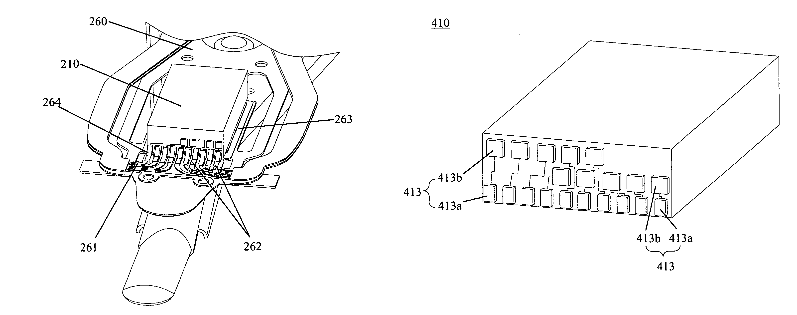
[0039]Various preferred embodiments of the invention will now be described with reference to the figures, wherein like reference numerals designate similar parts throughout the various views. As indicated above, the invention is directed to a slider for a HGA of a disk drive unit, which includes a trailing surface, a plurality of connection pads arranged on the trailing surface adapted for both bonding the slider to a suspension of the head gimbal assembly and testing the performance of the slider. At least a part of the connection pads each includes a bonding portion and a testing portion electrically connected to the bonding portion and larger than the bonding portion, all the bonding portions and the rest part of the connection pads are arranged in a first row and the testing portions are arranged outside the first row. The slider of the present invention includes a plurality of connection pads, each of which includes a bonding portion and a testing portion. The bonding portions ...


PUM

PropertyMeasurementUnit
widthaaaaaaaaaa
dimensionaaaaaaaaaa
layer structureaaaaaaaaaa

Abstract

A slider for a head gimbal assembly includes a trailing surface, a plurality of connection pads arranged on the trailing surface adapted for both bonding the slider to a suspension of the head gimbal assembly and testing the performance of the slider. At least a part of the connection pads each comprises a bonding portion and a testing portion electrically connected to the bonding portion and larger than the bonding portion, all the bonding portions and the rest part of the connection pads are arranged in a first row and the testing portions are arranged outside the first row. The slider of the present invention has a new pad layout to facilitate bonding of the connection pads and permit to provide additional pads thereon to connect the additional sensors therein for precise reading and writing, thereby improving the performance of the slider. The invention also discloses a head gimbal assembly and a disk drive unit including the same.

Description

[0001]This application claims priority to Chinese Application No. 201010119175.6 filed Feb. 10, 2010, the entire contents of which are hereby incorporated by reference in this application.FIELD OF THE INVENTION[0002]The present invention relates to magnetic hard disk drive device and, more particularly, to a slider with a new pad layout, head gimbal assembly and disk drive unit with the same.BACKGROUND OF THE INVENTION[0003]One known type of information storage device is a disk drive device that uses magnetic media to store data and a movable read / write head that is positioned over the magnetic media to selectively read from or write to the magnetic media.[0004]FIG. 1 illustrates a conventional disk drive device and show a magnetic disk 101 mounted on a spindle motor 102 for spinning the disk 101. A voice coil motor arm 104 carries a head gimbal assembly (HGA) 100 that includes a slider 110 incorporating a read / write head. A voice-coil motor (VCM, not labeled) is provided for contro...

Claims


Application Information

Patent Timeline
Patent Type & Authority Patents(United States)
IPC IPC(8): G11B5/455G11B5/60G11B5/31
CPCG11B5/105G11B5/486G11B5/4853G11B5/455
Inventor CHOU, SHENKUANGXIAO, LUDING, JURENWONG, KAYIPWANG, YANBINPENG, LIPING
Owner SAE MAGNETICS (HK) LTD
Why Eureka
Try Eureka