Combined processing lathe and its tool post

a technology of combing lathes and tool posts, which is applied in the field of combing lathes, can solve the problems of long movement strokes, limited reduction of processing time per workpiece, and long selection time, so as to reduce the restrictions on processing flexibility, minimize unprocessing time, and extend processing flexibility

Active Publication Date: 2012-10-30
CITIZEN WATCH CO LTD
View PDF28 Cites 22 Cited by
  • Summary
  • Abstract
  • Description
  • Claims
  • Application Information

AI Technical Summary

Benefits of technology

[0035]A combined processing lathe provided with a tool post according to the invention can previously select, during when a workpiece is machined by a tool attached to one of a plurality of turrets of the tool post, a tool necessary for the following processing attached to another turret, and can move the tool necessary for the following processing attached to another turret to a processing position in a minimum period of time by linearly moving the tool post in a Y-axis direction right after the completion of the current processing, to thereby start the following processing.
[0036]Further, it also becomes possible to simultaneously conduct processings in such a manner that the processing is performed on a workpiece held by a first spindle using a tool held by a certain turret while the processing is performed on another workpiece held by a second spindle using a tool 2 held by another turret.
[0037]In addition, each of the turrets can be turned at an arbitrary angle to perform processings, so that it also becomes possible to perform, on the workpiece held by the first spindle and the workpiece held by the second spindle, boring using drills having different and arbitrary inclinations with respect to center axes of the respective workpieces, processing of a groove and a surface with the use of milling, turning and boring, and the like, which results in largely extending the flexibility of processing.
[0038]Accordingly, it is possible to minimize the unprocessing time and to lower the restrictions on the flexibility of processing, which enables to remarkably reduce the processing time per one workpiece.

Problems solved by technology

However, in such a combined processing lathe in which the tool held by the tool spindle being the single spindle is changed by the tool changer according to each processing content, although the flexibility regarding the number of tools and a processing method conducted by the combined processing lathe is high, since the tool has to be changed at every processing step in which a different tool is used, the time for changing tools, namely, an unprocessing time has to be provided, which brings a limitation to the reduction in the processing time per one workpiece.
However, if the tools are attached separately in the vicinity of both end portions of the turret, there is a problem that a movement stroke becomes long and the selection time also becomes long.
Accordingly, the time for selecting the tool, namely, the unprocessing time has to be provided, resulting that the reduction in the processing time per one workpiece cannot be fully realized.
Further, since disposition angles of the tools are decided depending on the number of divisions of the side surfaces of the tool post head in its rotational direction, there are a lot of restrictions on flexibility of processing in such a case where, for example, processing on a workpiece held by a first spindle and processing on a workpiece held by a second spindle are simultaneously conducted, and the tool post cannot be used effectively, which also results in creating a problem when reducing the processing time per one workpiece.
However, it is not possible to previously select, during when the processing is performed using the cutter (tool) of one of the turrets, a cutter (tool) to be used for the following processing by dividedly rotating the other turret.
However, the turrets cannot be dividedly rotated separately and independently, so that also in this case, it is not possible to previously select, during when the processing is performed using the tool of one of the turrets, a tool to be used for the following processing by dividedly rotating the other turret.
Accordingly, each of these turrets cannot fully reduce the time taken for selecting the tools, namely, the unprocessing time, resulting that the reduction in the processing time per one workpiece cannot be fully realized.
Further, there are a lot of restrictions on the flexibility of processing.

Method used


Image

  • Combined processing lathe and its tool post
  • Combined processing lathe and its tool post
  • Combined processing lathe and its tool post

Examples


Embodiment Construction

[0063]Hereinafter, preferred embodiments of the present invention will be described with reference to the attached drawings.

[0064]First, with reference to FIG. 1 to FIG. 3, explanations will be made regarding a configuration example of a combined processing lathe according to the invention and a basic configuration example of a tool post according to the invention included in the combined processing lathe.

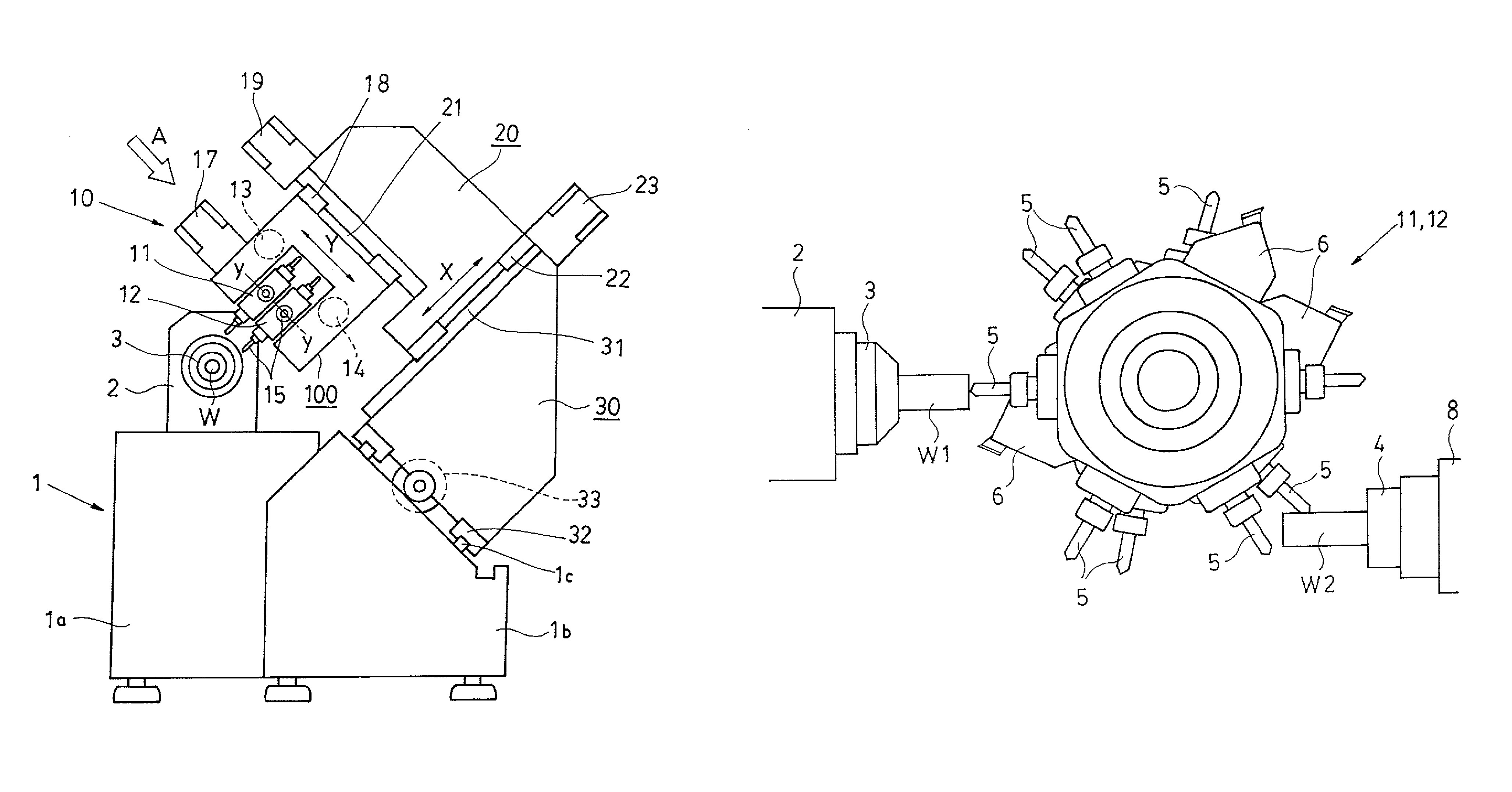
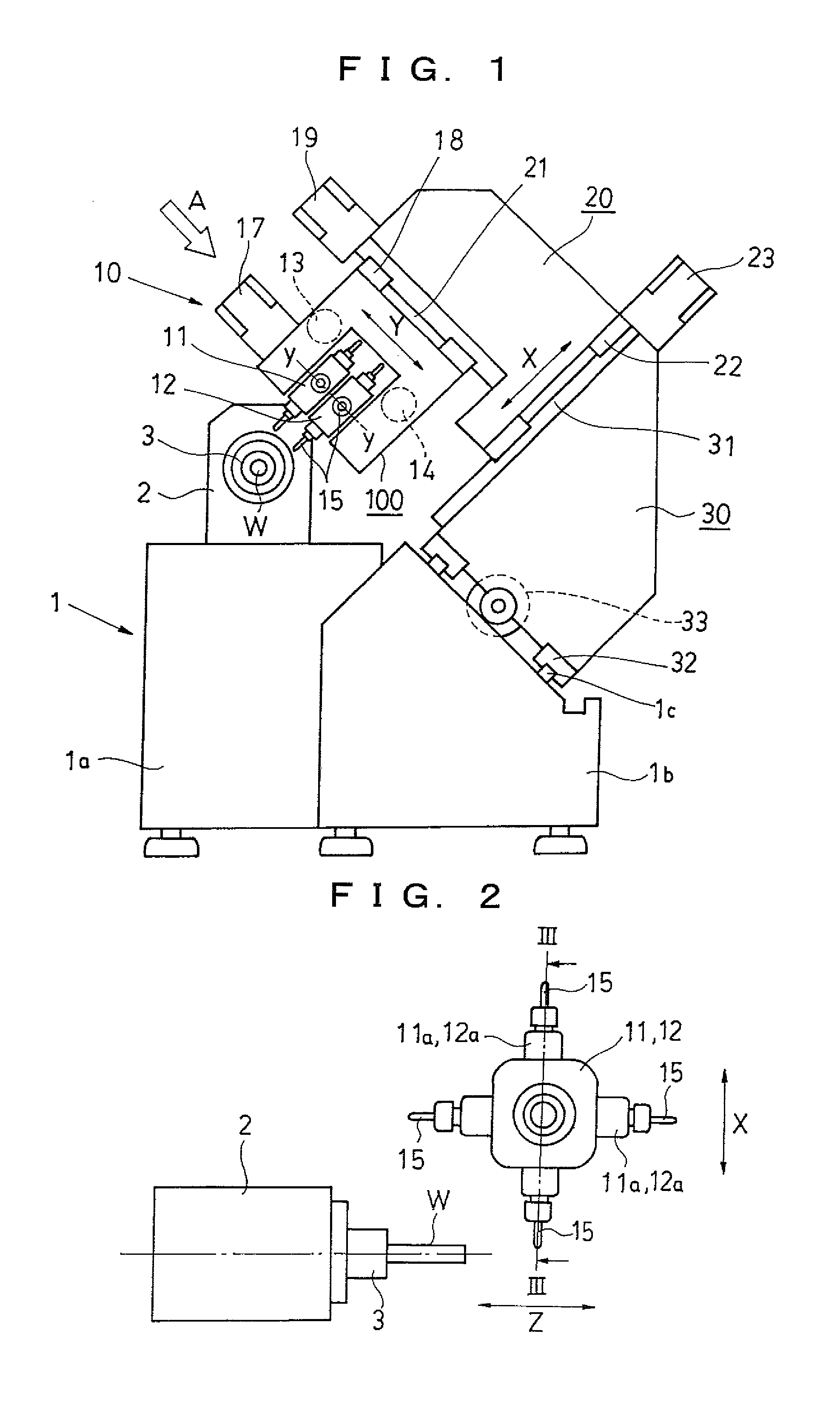
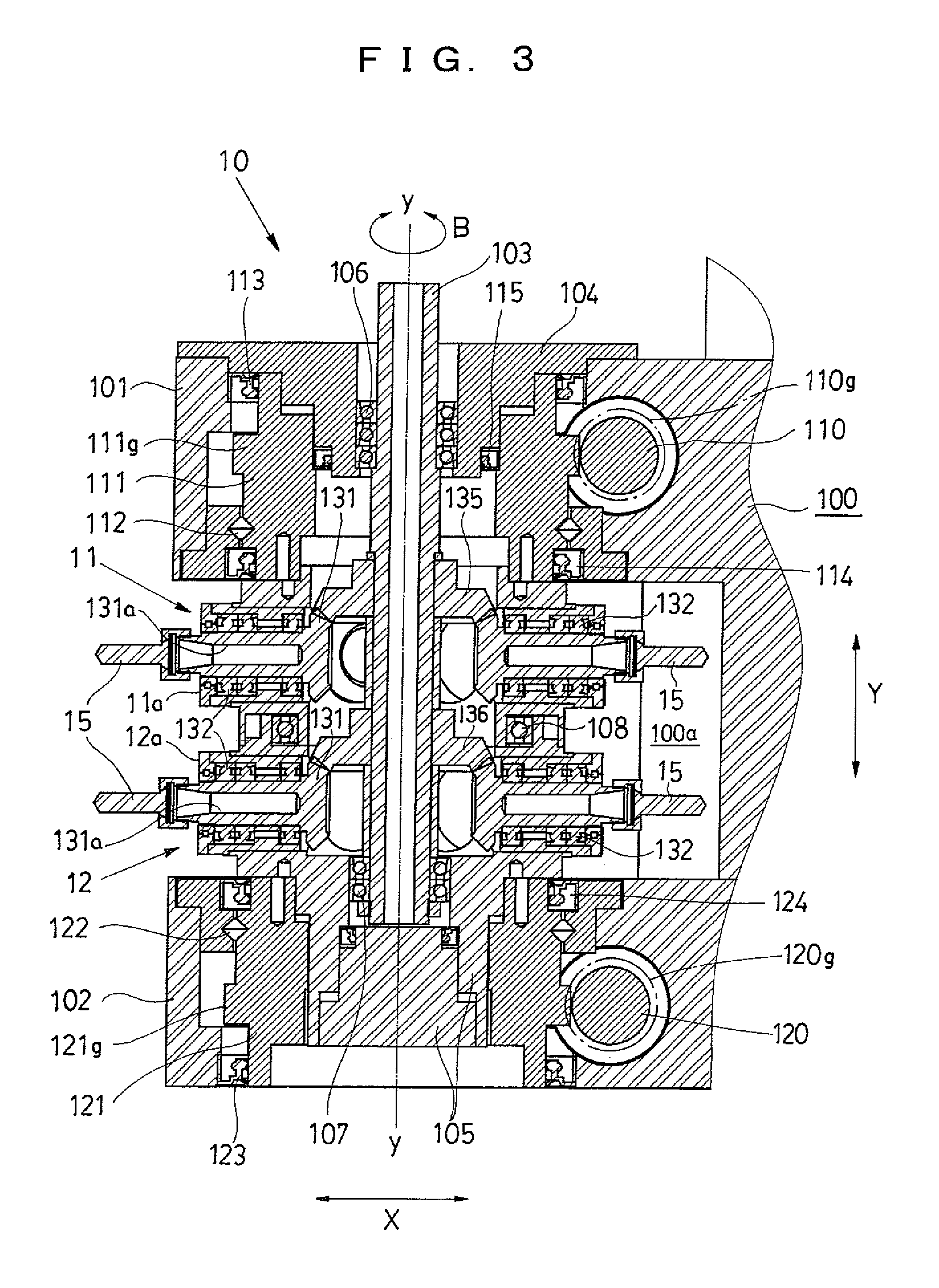
[0065]FIG. 1 is a schematic front view showing an entire configuration of the combined processing lathe, and FIG. 2 is a view showing a relation between a turret and a main spindle of the tool post seen from a direction indicated by an arrow A in FIG. 1. FIG. 3 shows an internal configuration of an entire tool post by enlarging its longitudinal section taken along III-III line in FIG. 2.

[0066]In FIG. 1, a headstock 2 supporting a rotatable main spindle 3 is mounted on a headstock supporting part 1a of a bed 1. The headstock 2 can be moved in a Z-axis direction being orthogonal to t...


PUM

PropertyMeasurementUnit
rotationaaaaaaaaaa
angleaaaaaaaaaa
flexibilityaaaaaaaaaa

Abstract

Turrets (11, 12), which can rotate about a common axis (y-y) and on the outer peripheral surfaces of which a plurality of tools (15) are radially installed, are disposed along the axis (y-y) in a turret housing (100). Respective turrets (11, 12) can be dividedly rotated by separate turret driving motors (13, 14).

Description

TECHNICAL FIELD[0001]The invention relates to a combined processing lathe (multiple turning center) performing a plurality of different kinds of processings (machinings) on a workpiece and a tool post being equipped in the lathe and selectably holding a plurality of tools used for the processings.BACKGROUND TECHNOLOGY[0002]A lathe generally performs processing by abutting a tool such as a cutting tool being a cutter against a workpiece for machining which is rotationally driven by a main spindle.[0003]Further, a lathe which performs a plurality of different kinds of processings, namely, combined processing on a workpiece is also in wide use, and various types of lathes or machine tools such as disclosed in, for example, Patent Documents 1 to 5 are known.[0004]Patent Document 1: JP H11-138374 A[0005]Patent Document 2: JP H10-15702 A[0006]Patent Document 3: EP 1270145 A2[0007]Patent Document 4: JP S62-236607 A[0008]Patent Document 5: JP H7-227704 A[0009]A combined processing lathe dis...

Claims


Application Information

Patent Timeline
Patent Type & Authority Patents(United States)
IPC IPC(8): B23Q16/00B23Q5/04
CPCB23B3/165B23Q16/025B23Q39/024B23Q39/028B23Q2039/004Y10T29/5155Y10T82/2587Y10T29/5124Y10T29/5109Y10T29/5153Y10T82/2508B23B29/24B23B3/16B23B29/00
Inventor WATANABE, MASAHIKOAOYAGI, ATSUSHI
Owner CITIZEN WATCH CO LTD
Why Eureka
Try Eureka