Interconnectable utility pole members

a utility pole and interconnection technology, applied in the direction of hose connection, mechanical apparatus, pipes, etc., can solve the problems of long length, high rot resistance of wood poles, insect infestation, etc., and achieve the effect of reducing the length of the press-fit, reducing the overall strength of the joint, and reducing the length of the join

Active Publication Date: 2012-11-06
MCWANE GLOBAL
View PDF32 Cites 19 Cited by
  • Summary
  • Abstract
  • Description
  • Claims
  • Application Information

AI Technical Summary

Benefits of technology

[0005]The present invention is directed to a metal utility pole and in particular to a hollow, centrifugally cast, ductile iron utility pole member having a tapered exterior and variable wall thickness for providing a shortened press-fit, slip joint between interconnected pole members. The shortened joint length requires less metal than conventional press-fit, slip joints while maintaining or improving the overall strength of the joint. This is accomplished by increasing the wall thickness of one or both interconnected pole members along the joint relative to the wall thickness of the body or mid-section of the pole members. This occurs by increasing the pole member wall thickness along the bottom end or butt of a pole member, the top end of the member or both.

Problems solved by technology

However, many modern utility pole uses require longer lengths than are practical, or even possible, with wood, and wood poles are highly susceptible to rot, insect infestation, bird attack and high winds.
Additionally, construction of wooden poles requires that the pole be of one piece of uncut wood which creates difficulties in transporting and erecting long poles.
Concrete utility poles, however, are expensive to produce, heavy and require special heavy duty equipment to load, transport, unload and install.
Further, the greater weight of concrete poles precludes the use of very long poles.
The widespread use of metal poles however has been limited since steel poles are expensive to produce and aluminum alloy utility poles do not have sufficient strength to be used in high lateral force environments.
Consequently, the cost of manufacturing the pole increases.
Lastly, a joint length where L / D=1.5 equates to a large overlap between interconnected pole members, and thus a large amount of wasted utility pole length.

Method used


Image

  • Interconnectable utility pole members
  • Interconnectable utility pole members
  • Interconnectable utility pole members

Examples


Embodiment Construction

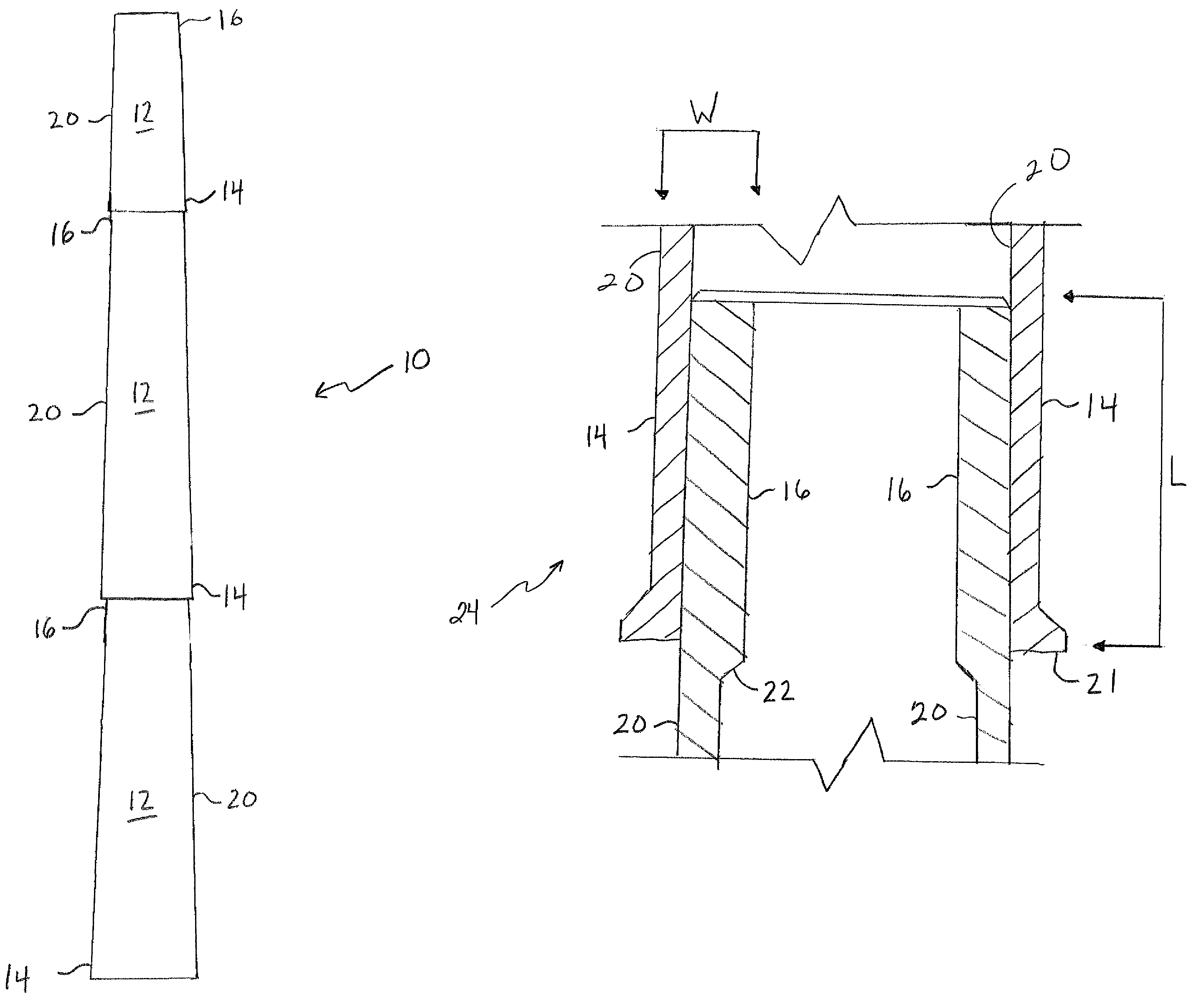
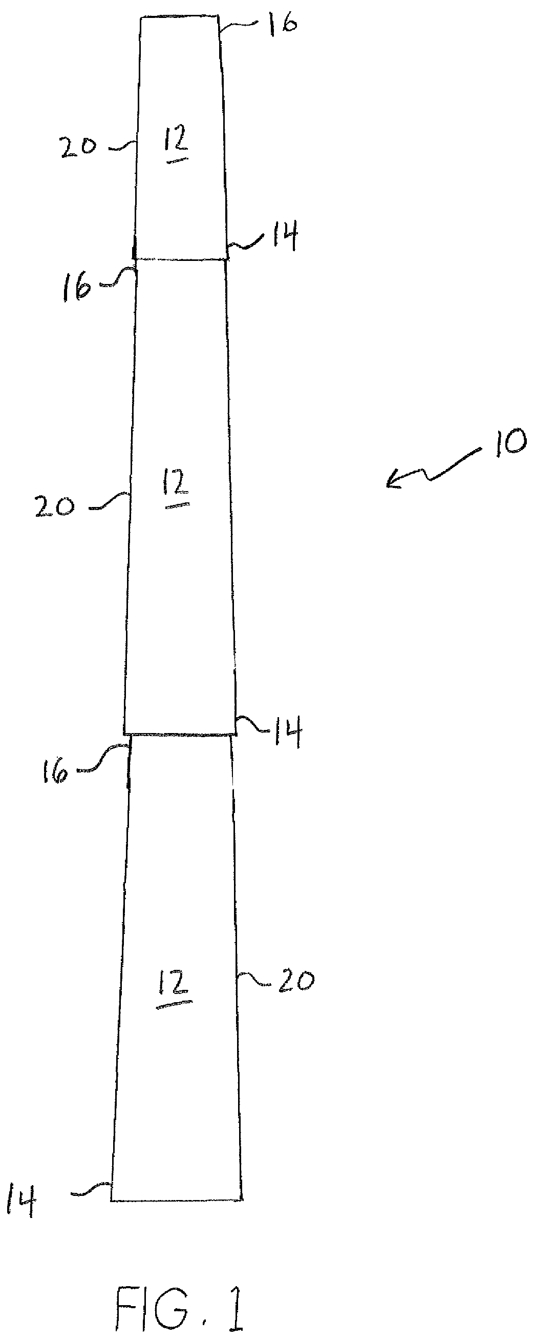
[0015]FIG. 1 depicts a hollow, utility pole 10 composed of separate and interconnected ductile iron, pole members 12 in accordance with the preferred embodiment of the present invention, each of members 12 having a tapered exterior shape. Preferably, pole members 12 are centrifugally cast using methods well known in the art. Other less well known methods can also be used including, for example, the centrifugal casting methods described in U.S. Patent Application Publication No. 2008 / 0023172 A2 and U.S. Pat. No. 5,784,851. As shown, utility pole 10 is built by stacking pole members 12, end to end, with a bottom end section 14 of one pole member 12 being supported directly on top of and overlapping a top end section 16 of another pole member 12. The overlap portion defines a slip joint between interconnected pole members 12 having a joint length L.

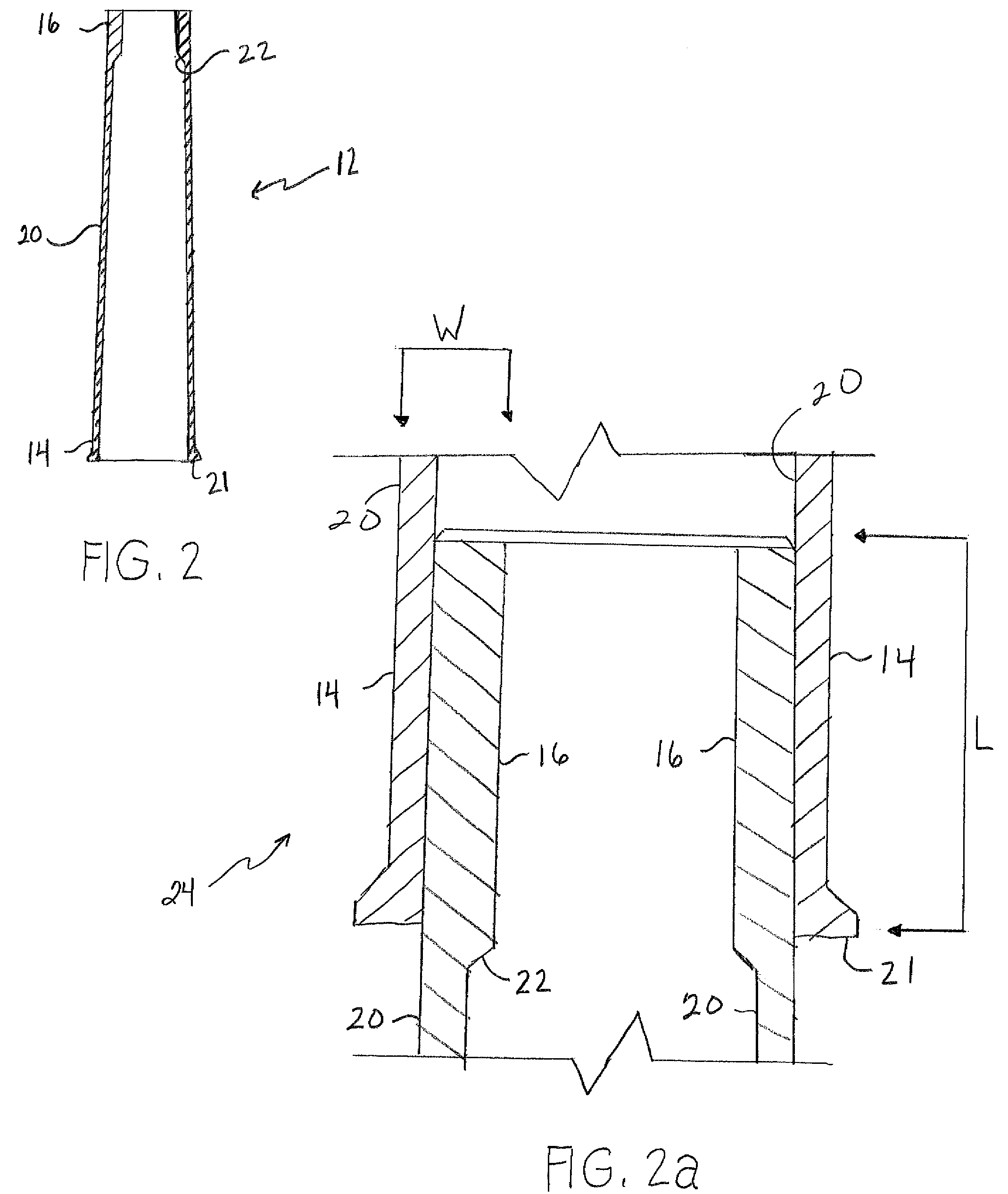
[0016]It has been found that by providing pole members 12 with a variable wall thickness, as specifically described herein, the joint lengt...


PUM


Abstract

A metal utility pole including a hollow, centrifugally cast, ductile iron utility pole member having a tapered exterior and variable wall thickness for providing a shortened press-fit, slip joint between interconnected pole members. The shortened joint length requires less metal than conventional press-fit, slip joints while maintaining or improving the overall strength of the joint. This is accomplished by increasing the wall thickness of one or both interconnected pole members along the joint relative to the wall thickness of the body or mid-section of the pole members.

Description

FIELD OF THE INVENTION[0001]The present invention relates to a multi-section utility pole and more particularly to a hollow, centrifugally cast, iron utility pole member having a tapered exterior and variable wall thickness for providing a shortened press-fit, slip joint between interconnected pole members.BACKGROUND OF THE INVENTION[0002]The oldest known method in the art of utility pole construction is the use of wooden poles, such as those commonly used for telephone lines. However, many modern utility pole uses require longer lengths than are practical, or even possible, with wood, and wood poles are highly susceptible to rot, insect infestation, bird attack and high winds. Additionally, construction of wooden poles requires that the pole be of one piece of uncut wood which creates difficulties in transporting and erecting long poles. To overcome the shortcomings of wood utility poles, solid concrete poles are often used. Concrete utility poles, however, are expensive to produce...

Claims


Application Information

Patent Timeline
Patent Type & Authority Patents(United States)
IPC IPC(8): F16L25/14E04C3/00
CPCE04H12/342E04C3/32E04H12/08
Inventor KEEL, MICHAEL CHAIN
Owner MCWANE GLOBAL
Why Eureka
Try Eureka