High-lift system for an aircraft

a technology for aircraft and lifts, applied in the direction of wing adjustment, wings, transportation and packaging, etc., can solve the problems of increasing the incidence angle, increasing the aerodynamic lift, and lengthening the effective wing profile, so as to increase the incidence angle and increase the incidence angle

Active Publication Date: 2012-11-06
AIRBUS OPERATIONS GMBH
View PDF26 Cites 20 Cited by
  • Summary
  • Abstract
  • Description
  • Claims
  • Application Information

AI Technical Summary

Benefits of technology

[0013]The rotation point about which the flap can pivot can be formed by a second joint which is located further to the rear of the flap with respect to the direction of flow of the air flowing around the wing and is coupled to a third joint, which is arranged on the wing, via a lever by way of which the rear part of the flap is drawn downwards in the sense of increasing the incidence angle as the extension movement increases.
[0014]The rotation point about which the flap can pivot can be formed by a third joint which is arranged on the wing and by way of which a second joint, which is located in the rear area of the flap is coupled via a lever by way of which the rear part of the flap is drawn downwards in the sense of increasing the incidence angle as the extension movement increases.
[0020]According to another embodiment, the drive device by way of which the position of the kinematic element can be varied can be operated positively coupled to the actuating drive for the high-lift flap.

Problems solved by technology

The flap is extended in an entirely general manner in a movement which on the one hand comprises movement of the flap with respect to the wing to the rear, and thus lengthening of the effective wing profile, and on the other hand an increase in the incidence angle of the flap with the profile curvature being increased, thus resulting in an increase in the aerodynamic lift.

Method used


Image

  • High-lift system for an aircraft
  • High-lift system for an aircraft
  • High-lift system for an aircraft

Examples


Embodiment Construction

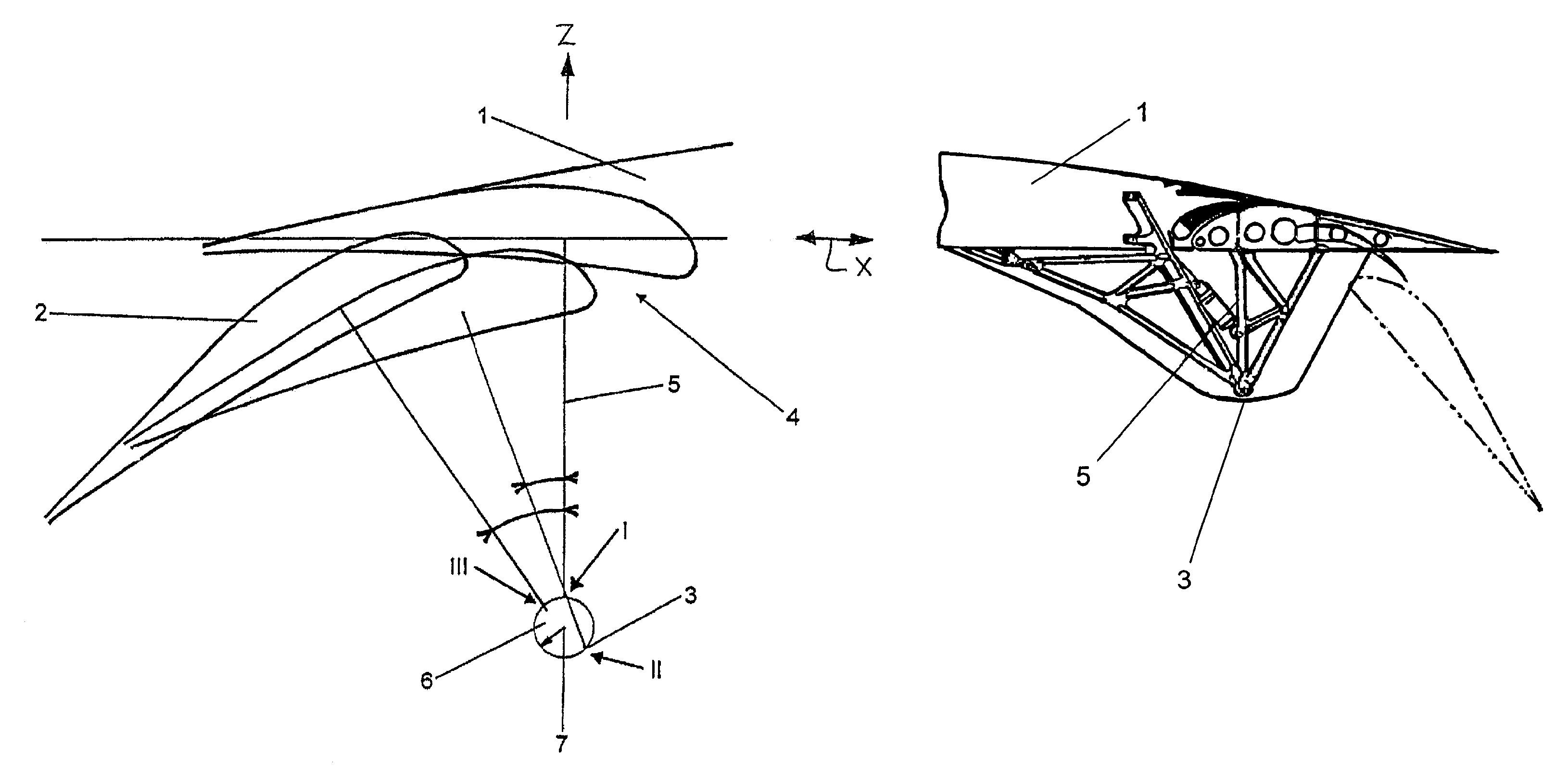
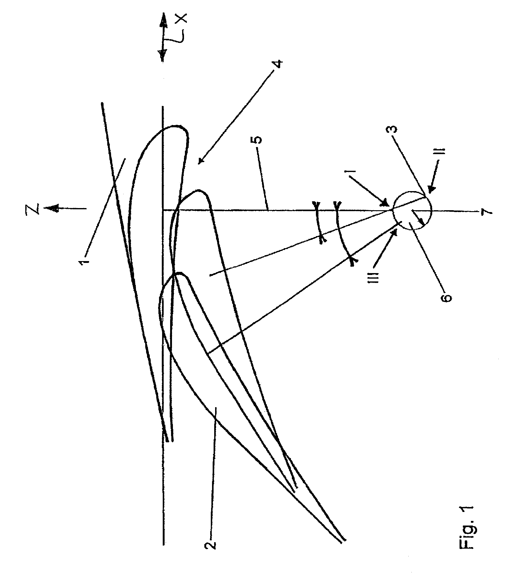
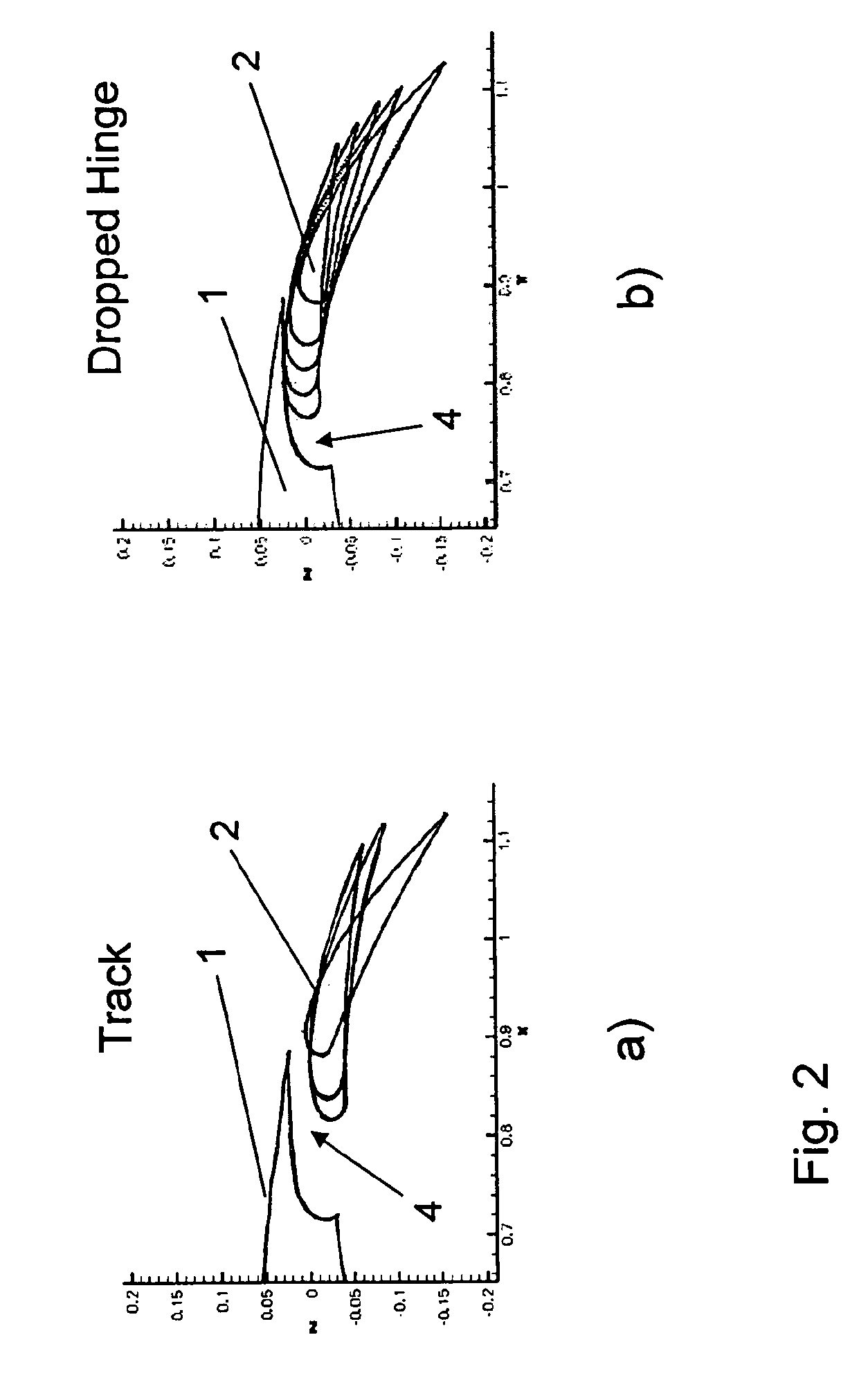
[0043]FIGS. 1 and 4 show dropped hinge flap kinematics, in which the high-lift flap 2 which is arranged on the mainplane 1 of the aircraft is mounted on a rotating arm or flap lever 5 such that it can pivot about a rotation point 3 which is provided under the wing 1. FIG. 4 shows the flap 2 in the retracted position, in which it continues the wing profile continuously essentially without any gap, and in a completely extended position, corresponding to a landing position, with the flap lever 5 not being illustrated in the latter case, in order to improve the clarity. A hydraulic actuator can be provided as the actuating drive, and is coupled between the flap lever 5 and a point arranged in a fixed position with respect to the mainplane 1. As shown in FIG. 2b, in the case of dropped hinge flap kinematics, the slot 4 between the wing 1 and the flap 2 opens only slowly at the start of the extension movement, because the flap 12 is moving on the circular arc.

[0044]In FIG. 1, the rotating...


PUM


Abstract

An exemplary high-lift system for an aircraft includes a wing, a high-lift flap coupled to the wing, a kinematic element which is driven by a drive device, and a flap lever structured and arranged to rotate via an actuating drive between a retracted position in which the high-lift flap complements a wing profile and a plurality of extended positions in which a slot of a given width is formed between the wing and the high-lift flap. A first end of the flap lever is coupled to the high-lift flap. A second end of the flap lever is coupled to the kinematic element and is capable of rotating relative thereto via a first rotation point. The kinematic element is structured and arranged to rotate relative to a second rotation point that is fixed in position relative to the wing. The first rotation point is separated by a predetermined distance from the second rotation point.

Description

CROSS-REFERENCE TO RELATED APPLICATIONS[0001]The present application is a U.S. National Stage of International Patent Application No. PCT / EP2007 / 006945 filed Aug. 6, 2007 which published as WO 2008 / 015024 on Feb. 7, 2008, and claims priority of German Patent Application No. 10 2006 036 464.3 filed Aug. 4, 2006.BACKGROUND OF THE INVENTION[0002]1. Field of the Invention[0003]The invention relates to a high-lift system for an aircraft and a method of using the system in an aircraft.[0004]2. Discussion of Background Information[0005]Large numbers of high-lift systems for aircraft are known. In general, these comprise high-lift flaps which are arranged on the aircraft mainplane and can be moved by means of an actuating drive between a retracted position, in which the flap continuously complements the wing profile essentially without any gap, and a plurality of extended positions, in which a slot of given width is formed between the wing and the flap and the flap is positioned at a predet...

Claims


Application Information

Patent Timeline
Patent Type & Authority Patents(United States)
IPC IPC(8): B64C3/50
CPCB64C9/16
Inventor SCHLIPF, BERNHARD
Owner AIRBUS OPERATIONS GMBH
Why Eureka
Try Eureka