Torsional oscillation damper

a torsional vibration and damper technology, applied in the direction of couplings, instruments, structural/machine measurement, etc., can solve the problems of insufficient damping properties, relatively complex construction, and the inability to employ a solution as a torsional vibration damper, etc., to achieve excellent damping properties, reduce construction complexity, and absorb large torque peaks

Inactive Publication Date: 2012-11-06
ASTURIA AUTOMOTIVE SYST
View PDF15 Cites 2 Cited by
  • Summary
  • Abstract
  • Description
  • Claims
  • Application Information

AI Technical Summary

Benefits of technology

[0007]It is an object of the invention to provide a torsional damper or torsional vibration damper which enables a relatively large rotation angle, has elastic properties and a simple construction in a small structure and is usable for a broad range of applications.
[0023]The invention solves the problem of providing a torsional vibration damper of simple design, which is flexibly adaptable to the most varied of applications and which is capable of achieving excellent damping properties, absorbing large torque peaks, and attaining large twist angles, by combining a damping medium with elastic elements.

Problems solved by technology

A disadvantage of the aforementioned solutions is the construction which is relatively complex from the manufacturing standpoint and the damping properties which are still insufficient for some applications.
No additional damping element for damping torsional vibrations between the components is provided, so that this solution cannot be employed as a torsional vibration damper.

Method used


Image

  • Torsional oscillation damper
  • Torsional oscillation damper

Examples


Embodiment Construction

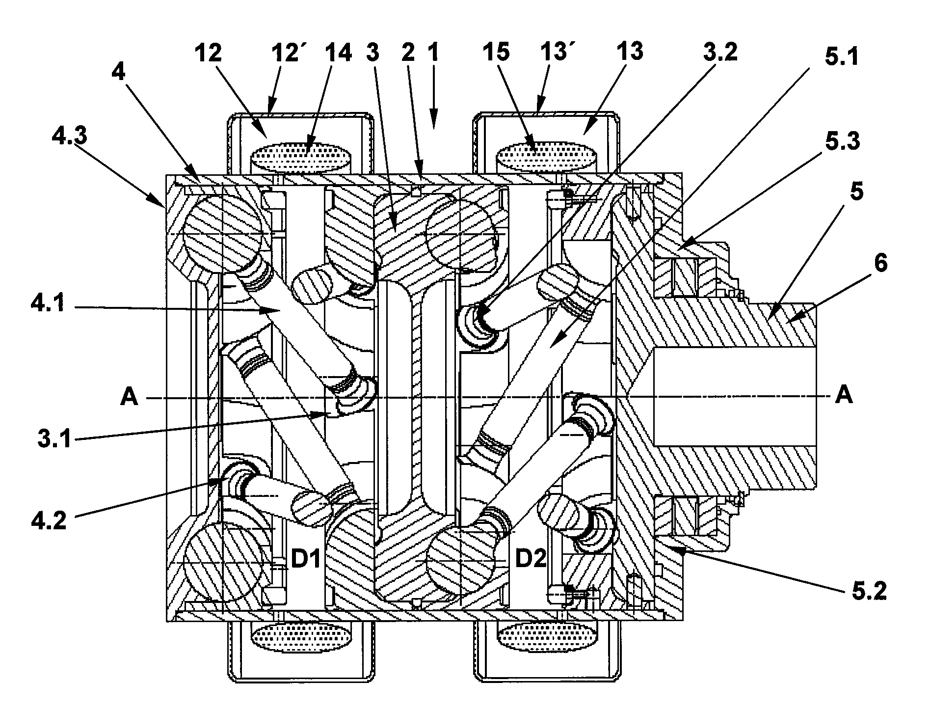
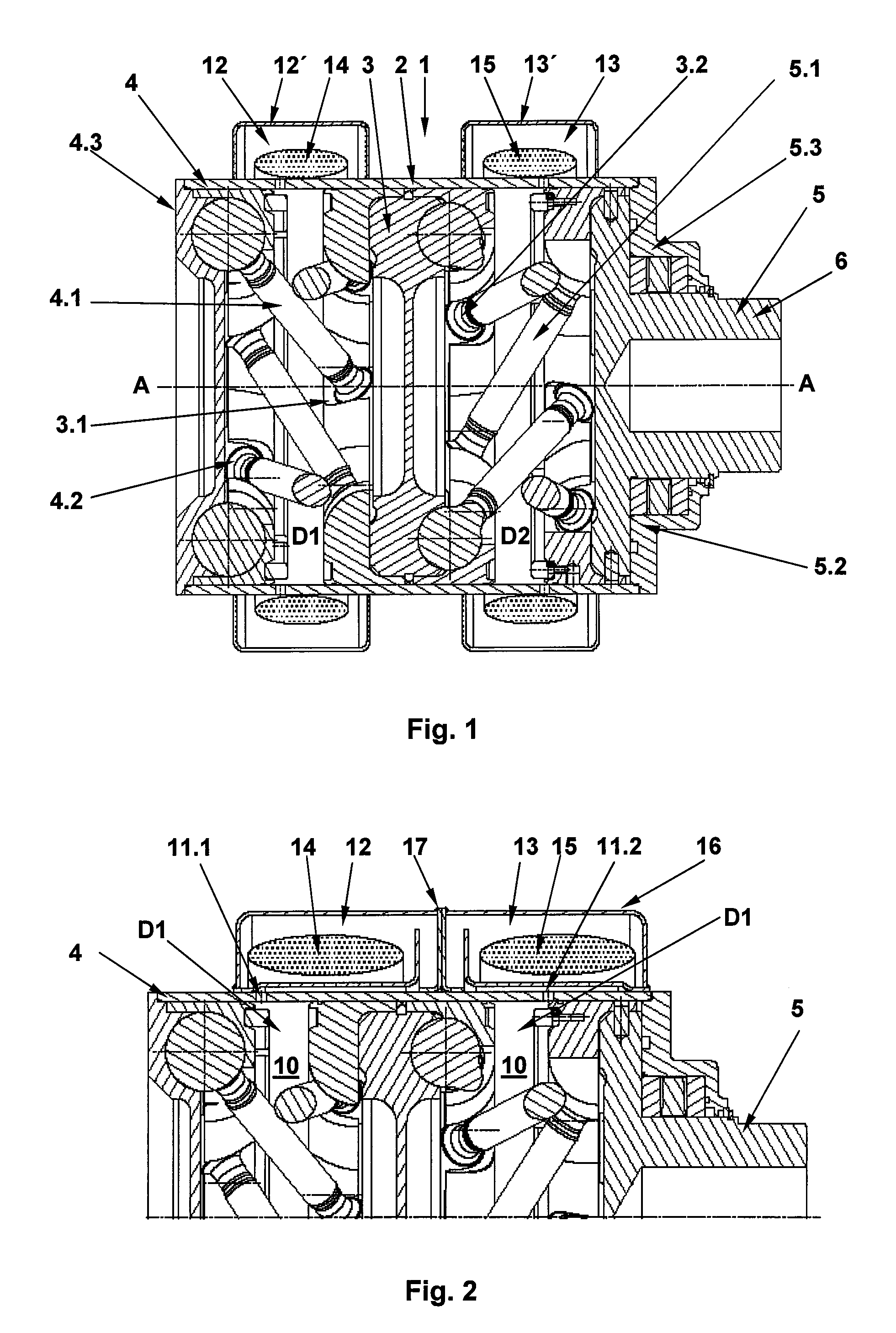
[0027]FIGS. 1 and 2 show a torsional vibration damper 1 which comprises an axially displaceable head part 3 and a rotary shaft 6 arranged in a housing 2. The first element 4 comprises the housing 2 and includes a first housing cover 4.3. The second element 5 comprises the rotary shaft 6 which extends through a second housing cover 5.2. The housing 2 (first element 4) and the rotary shaft 6 (second element 5) are rotatable relative to one another. For this purpose, the housing 2 (first element 4) is connected to the coupling part 3 via first rotatably mounted rigid coupling elements 4.1 and the rotary shaft 6 (the second element 5) is connected to the coupling part 3 via second rotatably mounted rigid coupling elements 5.1. The first coupling elements 4.1 are constructed in the form of ball bars and are rotatably mounted, on one side, with their ball-shaped ends in a first receptacle 4.2 of the first element 4 (at the housing 2) and, on the other side, in a receptacle 3.1 of the coup...


PUM


Abstract

A torsional vibration damper (1) comprising two elements (4, 5) which are rotatable relative to one another making use of at least one coupling part (3) which is arranged axially displaceable in a housing (2), in which the housing (2) is divided by the coupling element (3) into a first pressure chamber / partial chamber (D1) and a second pressure chamber / partial chamber (D2), and the first pressure chamber (D1) is connected to a first damping chamber (12) and the second pressure chamber (D2) is connected to a second damping chamber (13) and the first pressure chamber (D1) is filled with a damping medium (10) and the first damping chamber (12) is filled with the damping medium (10) and / or a first damping element (14) and the second pressure chamber (D2) is filled with a damping medium (10) and the second damping chamber (13) is filled with the damping medium (10) and / or a second damping element (15).

Description

BACKGROUND OF THE INVENTION[0001]The present invention relates a torsional vibration damper which is inserted between a driving system and a driven system and serves to dampen input and output vibrations and even out torque variations.[0002]Numerous torsional vibration dampers are known in which a drive element and a driven element are connected by a torsional spring for torque transmission. See, for example, US 2007 / 060400A1 (=DE 10 2005 037 996).[0003]Systems are also known wherein a torsional vibration is damped by spring elements which can be loaded in a radial or peripheral direction. See, for example, DE 198 12 303 A1 and U.S. Pat. No. 6,047,804 (=DE 197 33 334).[0004]U.S. Pat. No. 4,501,348 (=DE 32 28 673) describes a torsional vibration damper with a laterally displaceable damping element. The torsional vibration damper which is suited in particular for the clutch disk of a motor vehicle has two damper parts which are twistable relative to one another about a common rotation...

Claims


Application Information

Patent Timeline
Patent Type & Authority Patents(United States)
IPC IPC(8): F16D3/80F15B15/06
CPCF16F15/16
Inventor FREUND, WOLFGANGKISSLER, ANDREASSCHULZE, JUERGEN
Owner ASTURIA AUTOMOTIVE SYST
Why Eureka
Try Eureka