Package, method for manufacturing the same, piezoelectric vibrator, oscillator, electronic device, and radio-controlled timepiece

a piezoelectric vibrator and packaging technology, applied in the field of packaging, can solve the problems of increasing the drive voltage of the piezoelectric vibrator, reducing energy efficiency, and difficulty in increasing the degree of vacuum in the cavity, and achieve the effect of high reliability and high quality

Inactive Publication Date: 2012-11-06
SII CRYSTAL TECH
View PDF3 Cites 9 Cited by
  • Summary
  • Abstract
  • Description
  • Claims
  • Application Information

AI Technical Summary

Benefits of technology

[0011]According to this configuration, by disposing the plurality of kinds of gettering materials having different activation temperatures in the cavity, it is possible to activate the gettering materials at plural temperature ranges and absorb outgas present in the cavity. In this case, since outgas which was not completely absorbed by a gettering material having a low activation temperature can be absorbed by a gettering material having a higher activation temperature, it is possible to improve the degree of vacuum in the cavity. In this way, it is possible to provide a package having a low drive voltage.
[0035]According to the oscillator, electronic device, and radio-controlled timepiece according to the above aspect of the present invention, since they include the piezoelectric vibrator according to the above aspect of the present invention, it is possible to provide products having high quality and high reliability.

Problems solved by technology

As a result, there is a problem in that the drive voltage of the piezoelectric vibrator increases, and thus energy efficiency decreases.
However, the configuration disclosed in JP-A-2006-86585 has a problem in that it is difficult to increase sufficiently the degree of vacuum in the cavity.
For this reason, there is a problem in that it is difficult to absorb the outgas discharged from the bonding film immediately before the end of the gettering and during periods after the end of the gettering until the temperature of the piezoelectric vibrator decreases.
However, according to this method, since the gettering material will be degraded before bonding the lid board and the base board, there is a problem in that it is difficult to absorb the outgas present in the cavity after bonding.

Method used


Image

  • Package, method for manufacturing the same, piezoelectric vibrator, oscillator, electronic device, and radio-controlled timepiece
  • Package, method for manufacturing the same, piezoelectric vibrator, oscillator, electronic device, and radio-controlled timepiece
  • Package, method for manufacturing the same, piezoelectric vibrator, oscillator, electronic device, and radio-controlled timepiece

Examples


Embodiment Construction

[0053]Hereinafter, an embodiment of the present invention will be described with reference to the drawings.

Piezoelectric Vibrator

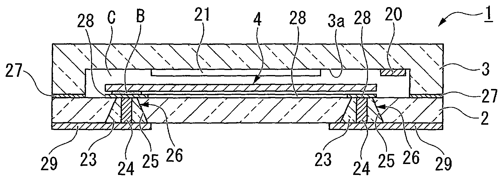
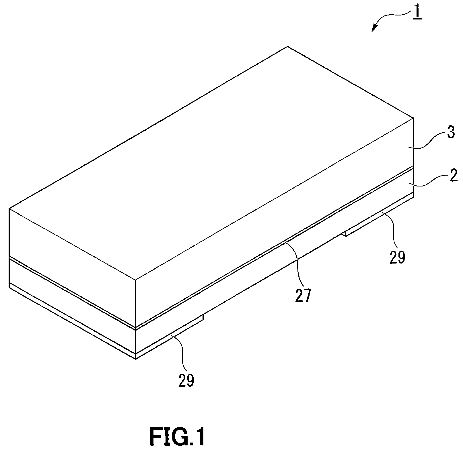
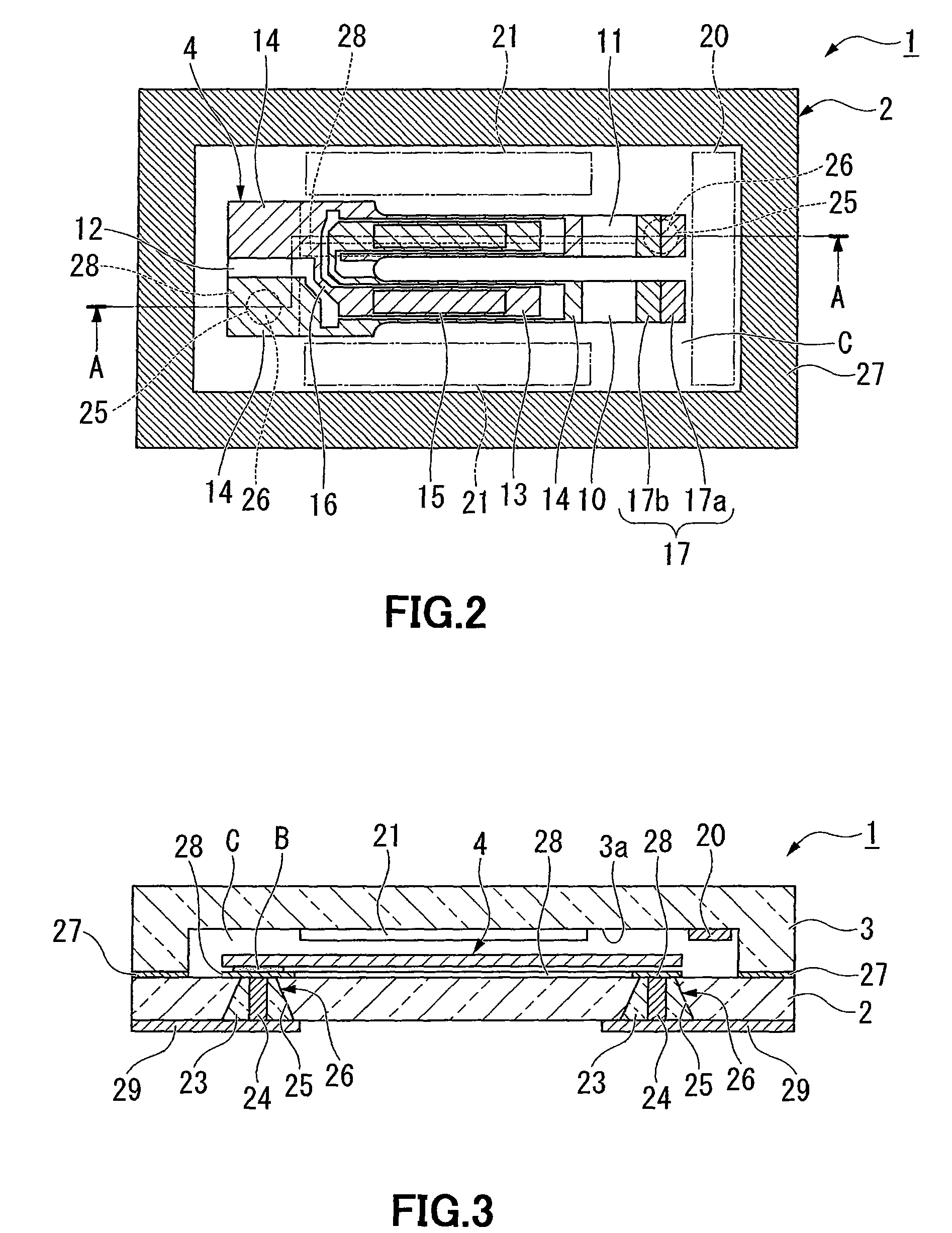
[0054]FIG. 1 is a perspective view showing an external appearance of a glass-packaged piezoelectric vibrator according to an embodiment. FIG. 2 is a top view showing an inner structure of the piezoelectric vibrator shown in FIG. 1 when a piezoelectric vibrating reed is viewed from above with a lid board removed. FIG. 3 is a sectional view of the piezoelectric vibrator taken along the line A-A in FIG. 2, and FIG. 4 is an exploded perspective view of the piezoelectric vibrator.

[0055]As shown in FIGS. 1 to 4, a piezoelectric vibrator 1 of the present embodiment is an SMD-type piezoelectric vibrator which is formed in the form of a box laminated in two layers of a base board 2 and a lid board 3 and in which a piezoelectric vibrating reed 4 is accommodated in a cavity C (see FIG. 2) at an inner portion thereof.

[0056]In FIG. 2, gettering materials 20 and 21 to b...


PUM

PropertyMeasurementUnit
bonding temperatureaaaaaaaaaa
voltageaaaaaaaaaa
resonance frequenciesaaaaaaaaaa

Abstract

Providing a package and a method for manufacturing the package capable of achieving improvement in the degree of vacuum in the cavity, and to provide a piezoelectric vibrator, an oscillator, an electronic device, and a radio-controlled timepiece. There is provided a package which includes a plurality of kinds of gettering materials 20, 21 having different activation temperatures and which are capable of being activated by heating is disposed in the cavity C.

Description

RELATED APPLICATIONS[0001]This application claims priority under 35 U.S.C. §119 to Japanese Patent Application No. 2009-194476 filed on Aug. 25, 2009, the entire content of which is hereby incorporated by reference.FIELD OF THE INVENTION[0002]The present invention relates to a package, a method for manufacturing the package, a piezoelectric vibrator, and an oscillator, an electronic device, and a radio-controlled timepiece.BACKGROUND ART[0003]Recently, a piezoelectric vibrator (package) utilizing quartz or the like has been used in a cellular phone and a portable information terminal as the time source, the timing source of a control signal, a reference signal source, and the like. The piezoelectric vibrator of this type is proposed in a variety of forms, and an SMD-type piezoelectric vibrator is one example. The SMD-type piezoelectric vibrator includes, for example, a base board and a lid board which are bonded to each other, a cavity formed between the two boards, and a piezoelect...

Claims


Application Information

Patent Timeline
Patent Type & Authority Patents(United States)
IPC IPC(8): H01L41/22H03H9/215H01L41/053H01L23/02H01L23/26H03B5/32H03H3/02H03H9/02
CPCH03H9/1021H03H9/21G04R20/10Y10T29/42H03H2003/0492H03H2003/0478
Inventor ARATAKE, KIYOSHISUGIYAMA, TAKESHIFUKUDA, JUNYA
Owner SII CRYSTAL TECH
Why Eureka
Try Eureka