Injection-locked frequency dividing apparatus

a frequency dividing apparatus and injection-locked technology, which is applied in the direction of oscillator generators, pulse techniques, counting chain pulse counters, etc., can solve the problems of affecting the application of the frequency divider, the lock range of the injection-locked effect when signals having the same phase are input, and the complexity of the mixed result produced by the foregoing circuit, etc., to achieve the effect of improving the overall performance of the frequency dividing apparatus, facilitating locking, and extending the lock rang

Inactive Publication Date: 2012-11-06
NAT TAIWAN UNIV OF SCI & TECH
View PDF5 Cites 7 Cited by
  • Summary
  • Abstract
  • Description
  • Claims
  • Application Information

AI Technical Summary

Benefits of technology

[0009]Accordingly, the present invention is directed to an injection-locked frequency dividing apparatus for eliminating nonlinear harmonic factors.
[0011]As described above, in the present invention, harmonic factors generated by nonlinear circuits are eliminated by using linear mixers to increase the injection-locked portion in the frequency, so that the oscillation frequency can be easily locked, and the lock range thereof can be extended. Accordingly, the overall performance of the frequency dividing apparatus is improved.

Problems solved by technology

While designing a divide-by-3 injection-locked frequency divider, the injection-locked effect when signals having the same phase are input is not very ideal for the lock range is very narrow.
However, the mixed result produced by foregoing circuit is very complicated.
Because the power is distributed over a broad frequency domain and there is only a small amount of valid sub-harmonic power, the lock range of the frequency divider is limited and accordingly the application of the frequency divider is affected.

Method used


Image

  • Injection-locked frequency dividing apparatus
  • Injection-locked frequency dividing apparatus
  • Injection-locked frequency dividing apparatus

Examples


Embodiment Construction

[0015]Reference will now be made in detail to the present preferred embodiments of the invention, examples of which are illustrated in the accompanying drawings. Wherever possible, the same reference numbers are used in the drawings and the description to refer to the same or like parts.

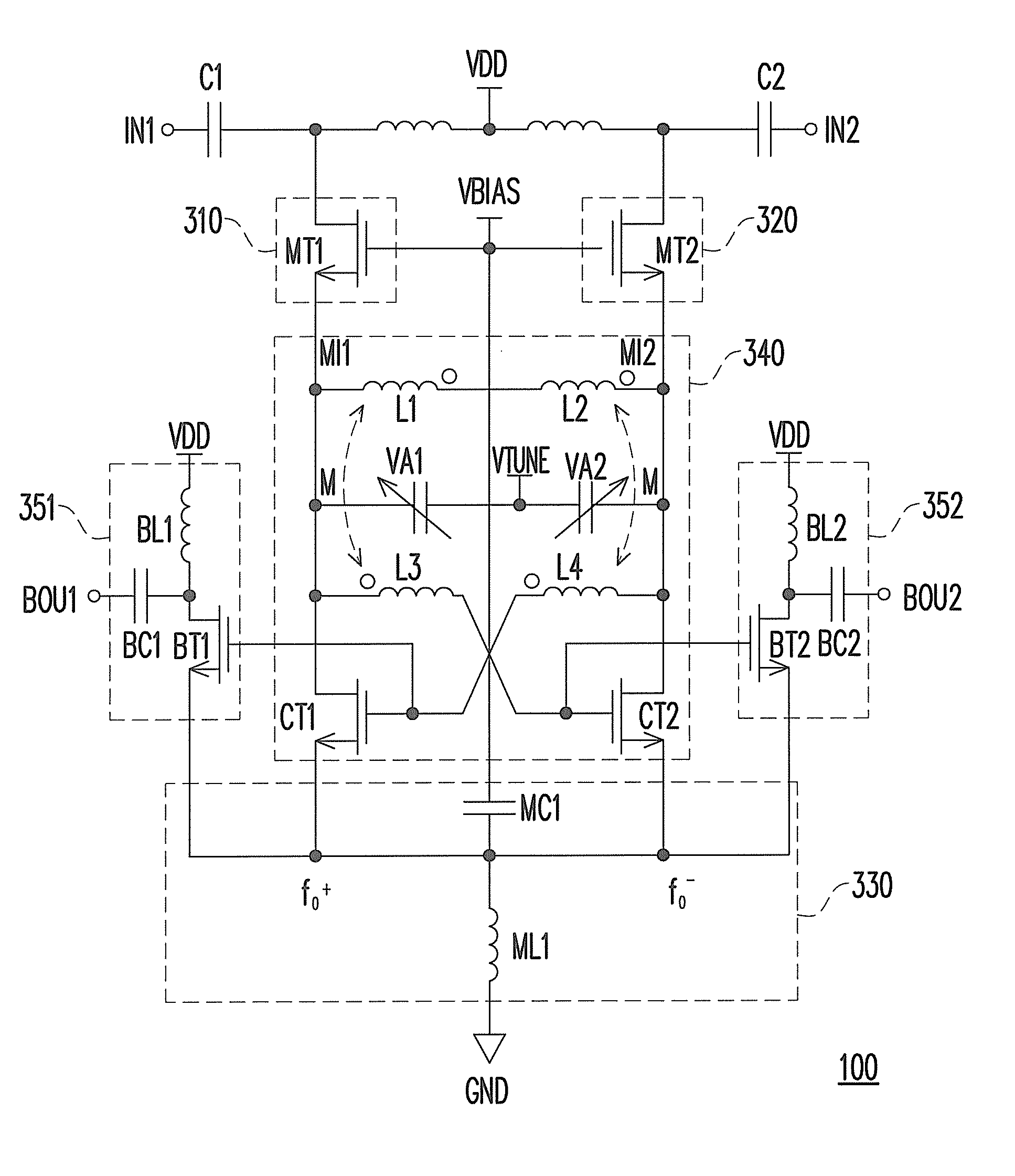
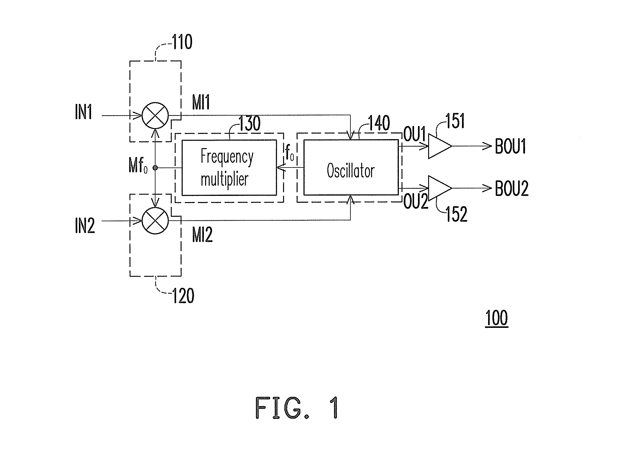
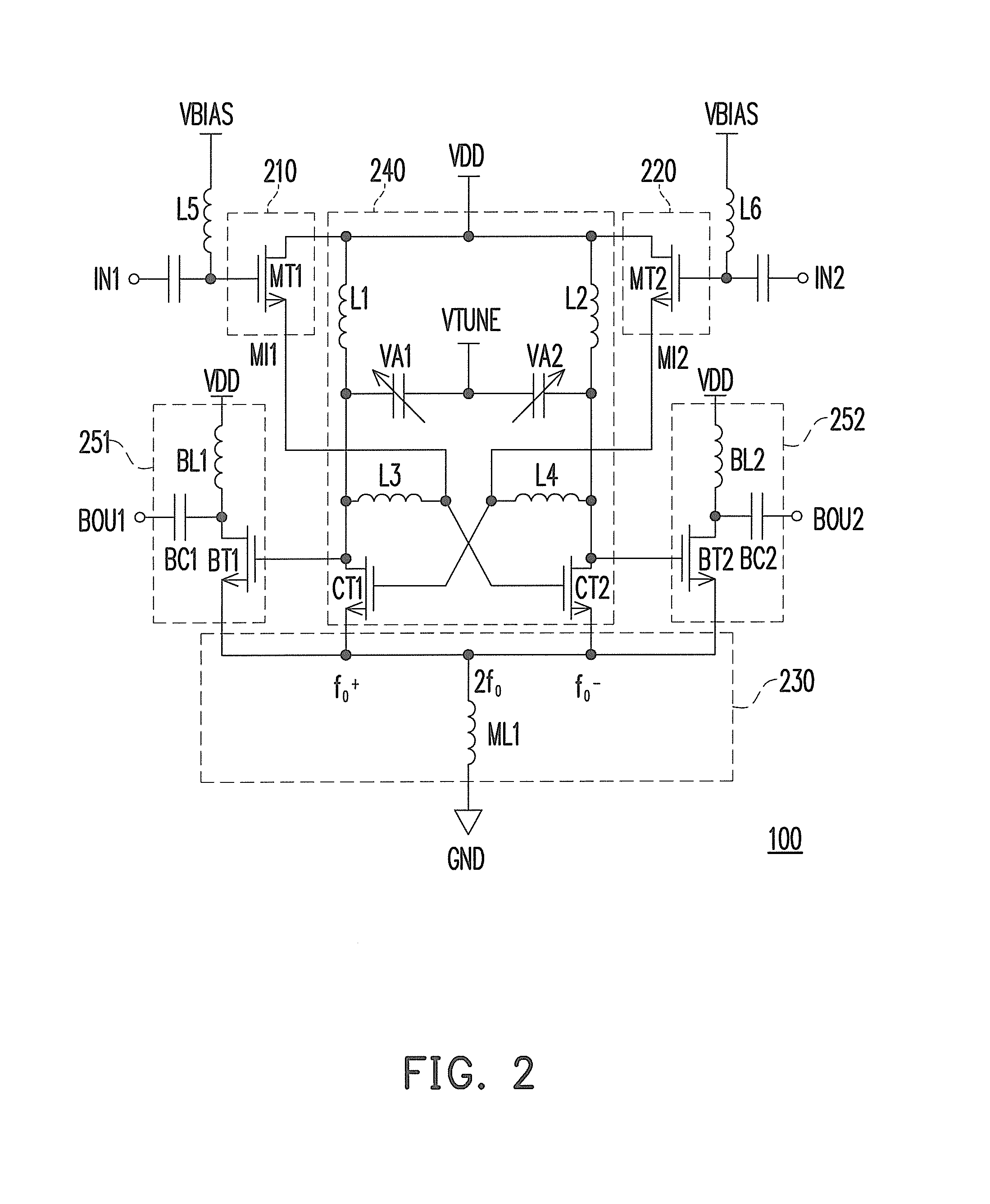
[0016]FIG. 1 is a diagram of an injection-locked frequency dividing apparatus 100 according to an embodiment of the present invention. Referring to FIG. 1, the injection-locked frequency dividing apparatus 100 includes linear mixers 110 and 120, a frequency multiplier 130, an oscillator 140, and output buffers 151 and 152. The frequency multiplier 130 receives a frequency signal fo and generates a multiple-frequency signal Mfo according to the frequency signal fo. In the present embodiment, the frequency of the multiple-frequency signal Mfo is twice the frequency of the frequency signal fo.

[0017]The linear mixers 110 and 120 are both coupled to the frequency multiplier 130 and both receive the multip...


PUM


Abstract

An injection-locked frequency dividing apparatus including a frequency multiplier, a first linear mixer, a second linear mixer, and an oscillator is disclosed. The frequency multiplier receives a frequency signal and generates a multiple-frequency signal accordingly. The first and the second linear mixer both receive the multiple-frequency signal and respectively receive a first input signal and a second input signal, wherein the phases of the first and the second input signal are complementary. The first and the second linear mixer respectively mix the multiple-frequency signal with the first and the second input signal to respectively generate a first mixed signal and a second mixed signal. The oscillator generates the frequency signal. The oscillator further receives the first and the second mixed signal and generates a first output signal and a second output signal accordingly, wherein the phases of the first and the second output signal are complementary.

Description

CROSS-REFERENCE TO RELATED APPLICATION[0001]This application claims the priority benefit of Taiwan application serial no. 99131227, filed on Sep. 15, 2010. The entirety of the above-mentioned patent application is hereby incorporated by reference herein and made a part of this specification.BACKGROUND OF THE INVENTION[0002]1. Field of the Invention[0003]The present invention generally relates to an injection-locked frequency dividing apparatus, and more particularly, to an injection-locked frequency dividing apparatus with linear mixers.[0004]2. Description of Related Art[0005]Along with the rapid development of communication technologies, the quantity and speed for transmitting data over communication networks have been drastically increased, and broad transmission bands have always been adopted in order to increase the transmission rate. In the wireless communication field, highly integrated and low-cost complementary metal-oxide-semiconductor (CMOS) chips are desired. While in a ...

Claims


Application Information

Patent Timeline
Patent Type & Authority Patents(United States)
IPC IPC(8): H03K21/00
CPCH03B5/1228H03B5/1212H03B5/1243H03B19/14H03B2200/0074H03B2200/0034
Inventor JANG, SHENG-LYANGCHEN, YU-SHENGCHANG, CHIA-WEILIU, CHENG-CHEN
Owner NAT TAIWAN UNIV OF SCI & TECH
Why Eureka
Try Eureka