Electromagnetic coil means

a technology of electromagnetic coil and means, which is applied in the field of electromagnetic coil means, can solve the problems of small inability to efficiently increase the distance between adjacent pins, and inability to achieve insulation performance between adjacent pins, so as to increase the distance between adjacents and increase the overall volume of electromagnetic coils. , increase the distance between solder joints

Active Publication Date: 2012-11-06
ZHEJIANG SANHUA INTELLIGENT CONTROLS CO LTD
View PDF37 Cites 8 Cited by
  • Summary
  • Abstract
  • Description
  • Claims
  • Application Information

AI Technical Summary

Benefits of technology

[0007]The technical problem to be solved by the present invention is to provide an electromagnetic coil means which has a structure designed to be capable of improving the insulation performance between solder joints of pin head portions, and facilitating the soldering operation, thus to ensure the stability and reliability of the operation of the electromagnetic coil means.
[0025]In the electromagnetic coil means provided in this invention, at least one group of the first and second groups of pins are bent, and a distance between adjacent said first and second head portions is larger than that between adjacent said first and second root portions. The increase of the distance between adjacent first and second head portions enables to increase the distance between solder joints of adjacent pin head portions without increasing the overall volume of the electromagnetic coil means, thus the insulation performance between solder joints of adjacent pin head portions is improved and soldering operation is facilitated, ensuring the stability and reliability of the operation of the electromagnetic coil means.

Problems solved by technology

However, due to the restriction caused by factors such as the overall volume of the electromagnetic coil means and the like, the distance between the pins can not be increased efficiently, which leads to a small distance between adjacent pins 11 in the prior art.
Therefore, the distances between head portions 111 of adjacent pins and between the solder joints thereof are small, so that the insulation performance between the solder joints between pin head portions 111 is deteriorated, and the soldering operation is inconvenient.

Method used


Image

  • Electromagnetic coil means
  • Electromagnetic coil means
  • Electromagnetic coil means

Examples


first embodiment

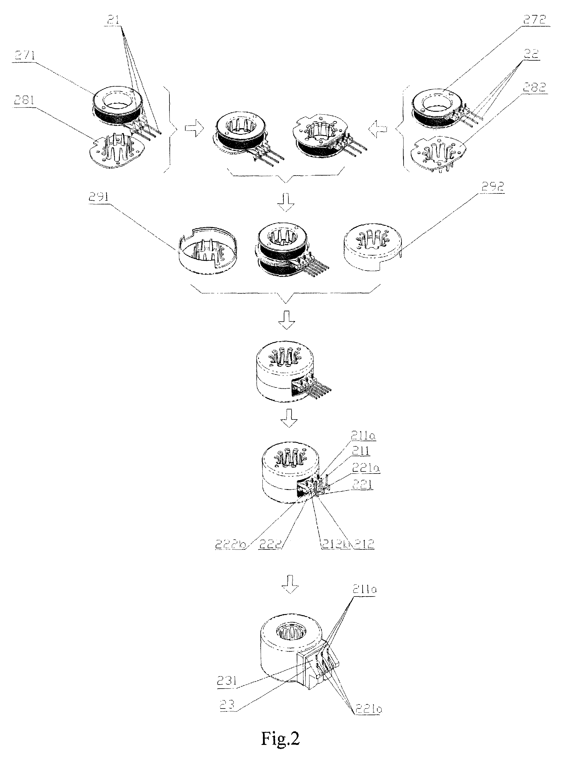
[0038]Reference is made to FIG. 2, which is an assembly flowchart of an electromagnetic coil means provided in the present invention.

[0039]The assembly process of the electromagnetic coil means provided is in the first embodiment of the present invention is as follows:

[0040]Enameled wire is wound onto an upper frame 271, and the ends of the enameled wire are connected with first root portions 212b of a first group of pins 21, forming an upper coil stator on which an upper electromagnetic polar board 281 is mounted. Enameled wire is wound onto a lower frame 272, and the ends of the enameled wire are connected with second root portions 222b of a second group of pins 22, forming a lower coil stator on which a lower electromagnetic polar board 282 is mounted. The upper coil stator mounted with the upper electromagnetic polar board 281 and the lower coil stator mounted with the lower electromagnetic polar board 281 are assembled together, forming an electromagnetic coil stator. The elect...

second embodiment

[0047]Reference is made to FIG. 3 which is a schematic view of the structure of an electromagnetic coil means provided in the present invention.

[0048]The second embodiment of the present invention is a variation of the first embodiment in which the shape of the terminal part 23 is varied. The bending direction of the pins in the second embodiment is the same as that in the first embodiment, thus a detailed description thereof is omitted.

[0049]In the second embodiment, the pin leading-out surface of the terminal part 23 includes an upper step surface 232 and a lower step surface 233 that is substantially parallel to the upper step surface 232. The first head portions 211a are substantially perpendicular to the upper step surface 232 and the second head portions 221a are substantially perpendicular to the lower step surface 233.

[0050]The bending method of pins in the second embodiment is the same as that in the first embodiment, thus a detailed description thereof is omitted.

[0051]By ...

third embodiment

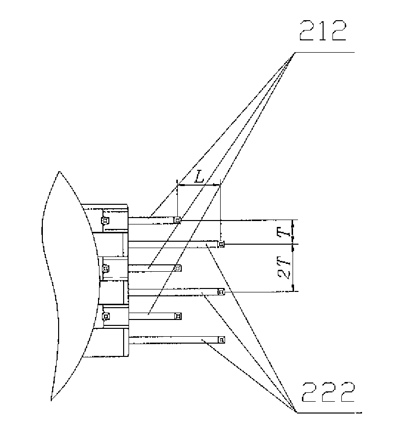
[0060]In the third embodiment, the pin leading-out surface is an inclined surface 234, and first and second groups of pins 21, 22 (both shown in FIG. 2) bend upward. Middle portions 211b between the first inner sections 212 (shown in FIG. 2) and the first head portion 211a are substantially perpendicular to the first inner sections 212, and an appropriate angle is formed between the first head portions 211a and the first middle portions 211b. Middle portions 221b between the second inner sections 222 and the second head portions 221a are substantially perpendicular to the second inner sections 222, and an appropriate angle is formed between the second head portions 221a and the second middle portions 221b. The first and second head portions 211a, 221a are substantially perpendicular to the inclined surface 234.

[0061]The first and second groups of pins 21, 22 described in last paragraph both bend upward relative to the electromagnetic coil means disposed as shown in FIG. 7.

[0062]Befo...


PUM

PropertyMeasurementUnit
angleaaaaaaaaaa
distanceaaaaaaaaaa
horizontal distanceaaaaaaaaaa

Abstract

The present invention discloses an electromagnetic coil means, comprising a terminal part and pins passing through the terminal part, wherein the pins are divided into a first group of pins connected with an upper coil stator and a second group of pins connected with a lower coil stator which are spaced apart from each other; the first group of pins comprises first outer sections with first head portions and first inner sections with first root portions; the second group of pins comprising second outer sections with second head portion and second inner sections with second root portions; the first and second head portions extend out from a pin leading-out surface of the terminal part, characterized in that, at least one group of the first and second groups of pins are bent, and a distance between adjacent said first and second head portions is larger than that between adjacent said first and second root portions. By this electromagnetic coil means, the distance of solder joints between adjacent head portions of pins is increased, thus the insulation performance between the solder joints is improved.

Description

FIELD OF THE INVENTION[0001]The present invention relates to the field of mechanical electronics, more particularly, to an electromagnetic coil means.THE RELATED ART[0002]Electromagnetic coil means may be applied in various fields. For example, it may be used as the coil of electronic expansion valve in an air-conditioner refrigeration system, which is a typical use thereof, or used as the stator part in a step motor, or used in an electronic device having a plurality of terminals connected with lead by means of soldering.[0003]Reference is made to FIG. 1, which is a schematic view showing the structure of a typical electromagnetic coil means in the prior art.[0004]The electromagnetic coil means in the prior art includes a terminal part 12 and some pins 11 passing through the terminal part 12. The pins 11 are divided into a first group of pins connected with an upper coil stator and a second group of pins connected with a lower coil stator, in which the first and the second groups o...

Claims


Application Information

Patent Timeline
Patent Type & Authority Patents(United States)
IPC IPC(8): H01F27/29H02K37/00
CPCH01F5/04H01F7/06H02K5/225H02K3/525H01F2007/1692H01F2007/062
Inventor WEI, XIANRANGYUAN, ZE
Owner ZHEJIANG SANHUA INTELLIGENT CONTROLS CO LTD
Why Eureka
Try Eureka