
Elevator car position detection system and method of determining a position of an elevator car in an elevator shaft

a technology of elevator car and detection system, which is applied in the direction of elevators, instruments, computer control, etc., can solve the problems of unreliable detection of beams, inability to determine the exact position of elevator cars, and serious errors, and achieves simple and cost-effective, easy-to-maintain effects

Inactive Publication Date: 2012-11-13
INVENTIO AG
View PDF11 Cites 11 Cited by
  • Summary
  • Abstract
  • Description
  • Claims
  • Application Information

AI Technical Summary

Benefits of technology

The present invention provides an elevator car position detection system that is reliable, does not require additional communication lines, is not sensitive to vibrations, and can accurately indicate the absolute position of an elevator car. The system employs a sensor stripe on the elevator shaft wall and an activation device on the elevator car to create a local electrical connection between the feed line and resistor line, which modifies the resulting resistance between the ends of the feed line and the resistor line. The control electronics based on the resulting resistance determine the elevator car position. The system is simple, cost-effective, suitable for a variety of applications, and easy to maintain. The absolute position of the car is directly obtained from the resulting resistance, eliminating the need for a memory or register to constantly keep the car position.

Problems solved by technology

It is a known problem that, since the suspension cables of elevators can change their length in time or due to temperature changes and because the winch that winds these cables has some errors due to slips or other unpredictable events, the exact position of an elevator car can not be determined solely by the positioning of the suspension system.
Such systems must be independent from the suspension system in that the detection should not rely on the length of the cable wound up or on the rotational position of the winch because this might lead to serious errors ranging from a few centimeters up to meters if very long suspension cables are used.
However, in both cases several disadvantages and difficulties arise: it is often a problem to guarantee a clear line of sight between the detector and the light source since the space between the ends of the elevator shaft and the elevator is usually occupied by the suspension cables, communication or power cables and other elements of the elevator system.
A further problem is that in very tall shafts (high rise elevators) even a small vibration of the car may cause significant deviation of the light beam rendering the detection of the beam and thus of the car's position unreliable.
Ensuring the cleanliness of the light source, the detector and in some cases the reflective mirror might also become a problem in certain cases.
However, such systems can only detect relative movement of the car and not absolute position and by that an error in the scanning can pass undetected for an extended period of time.
However, even if this system may work well in most cases, it is rather complicated in construction.
On one hand having additional cables between the shaft and car can be problematic because of the presence of the suspension ropes and other moving elements.
In open or glass covered shafts it is esthetically undesirable to have additional cables hanging.
On the other hand, radio communication between the car and the control system of the elevator motors in the shaft requires additional components and electric energy.
Interferences with other radio devices or even intentional jamming of the signal can render the system unreliable.

Method used


Image

  • Elevator car position detection system and method of determining a position of an elevator car in an elevator shaft
  • Elevator car position detection system and method of determining a position of an elevator car in an elevator shaft
  • Elevator car position detection system and method of determining a position of an elevator car in an elevator shaft

Examples


Embodiment Construction

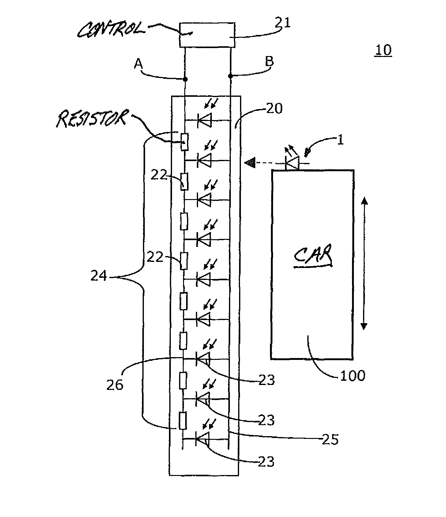
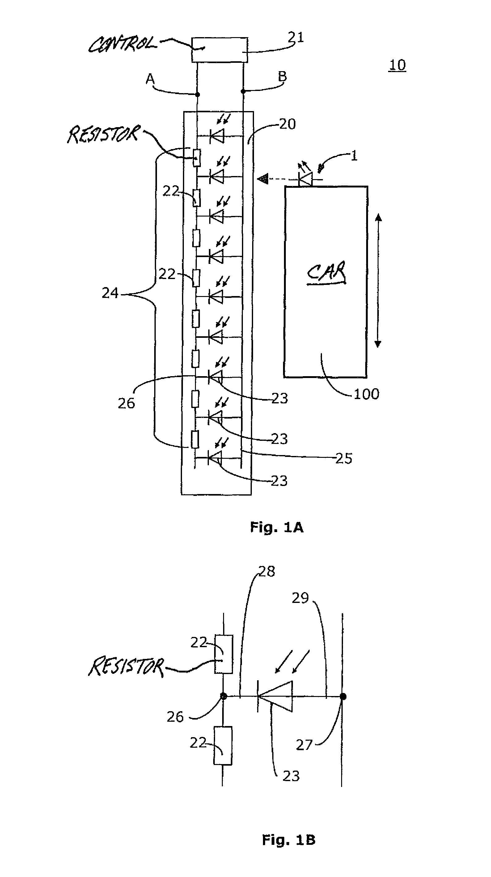
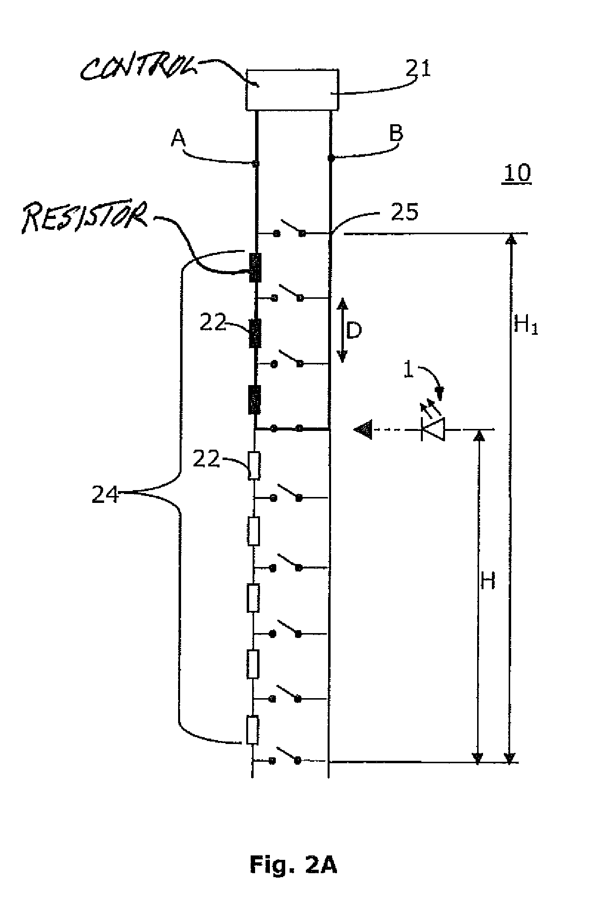
[0019]FIG. 1A shows the preferred embodiment of the elevator car position detection system 10. The idea behind the invention is the use of a sensor stripe 20 in combination with a light emitting device 1 mounted on top of an elevator car 100 and control electronics 21. The sensor stripe 20 comprises a vertical feed line 25 and a vertical resistor line 24 with optical sensors 23 positioned between them. As it is shown in FIG. 1B, the optical sensors 23 are positioned between a node 26 of the resistor line 24 and a node 27 of the feed line 25. In the preferred embodiment the optical sensor 23 is a photodiode or phototransistor which, when illuminated, conducts electricity to create a local electrical connection between the feed line 25 and resistor line 24 and thus modifying the resulting resistance Rres between an end or terminal A of the resistor line 24 and an end or terminal B of the feed line 25. The polarization of the optical sensor 23 is to be determined based on the way the s...


PUM


Abstract

Elevator cabin position detection system comprising an activation device mounted on an elevator car, a sensor stripe mounted on a sidewall of an elevator shaft and control electronics. The activation device, preferably a light emitting device, activates a portion of the sensor stripe which comprises a feed line, a resistor line and sensors positioned between these. The sensors, preferably optical sensors, when activated by the activation device, conduct electricity to create electrical connection between the feed line and resistor line and thus modify the resulting resistance between an end (A) of the resistor line and an end (B) of the feed line. The control electronics determines the exact position of the elevator cabin based on the resulting resistance between the end (A) of the resistor line and the end (B) of the feed line.

Description

FIELD OF THE INVENTION[0001]The present invention relates to elevator car position detection systems, which are capable to precisely indicate the exact vertical position of an elevator within the elevator shaft and a corresponding method of determining a position of an elevator car in an elevator shaft.BACKGROUND OF THE INVENTION[0002]It is a known problem that, since the suspension cables of elevators can change their length in time or due to temperature changes and because the winch that winds these cables has some errors due to slips or other unpredictable events, the exact position of an elevator car can not be determined solely by the positioning of the suspension system. This means that even if a direct relation exists between the number of rotations of the winch and the height of the car, several factors can affect this relation. For this reason, a dedicated positioning system is required to be able to precisely determine the actual position of the elevator car within the sha...

Claims


Application Information

Patent Timeline
Patent Type & Authority Patents(United States)
IPC IPC(8): B66B1/34
CPCB66B1/3492
Inventor FERREIRA, TEOFILO
Owner INVENTIO AG
Learn More